Steam traps
Ball float
Page 3 of 4
Dimensions/weights (approximate) in mm and kg
Size
A
A
B
C
D
PN/ASME
JIS/KS
DN15
150
150
107
102
51
DN20
150
150
107
102
53
DN25
160
170
125
65
100
E
F
G
Weight
Withdrawal distance
47
38
105
4.7
47
38
105
5.2
10
38
120
6.8
DN25
FTGS14-C
FTGS14
B
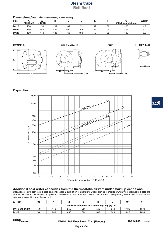
Capacities
��������
��������
������
������
������
������
������
����
����
����
����
DN15 and DN20
F
D
E
D
E
A
C
G
C
G
������
������
������
������
��
��
��
�� ��
����
����
Differential pressure bar (x 100 = kPa)
Additional cold water capacities from the thermostatic air vent under start-up conditions
Capacities shown above are based on condensate at saturation temperature. Under start-up conditions when the condensate is cold the
internal thermostatic air vent will be open and provides additional capacity to the main valve. The following table gives the minimum additional
cold water capacities from the air vent.
0.5
1 2 3 4.5
7 10
∆P (bar)
DN15 and DN20
DN25
Minimum additional cold water capacity (kg/h)
FTGS14 Ball Float Steam Trap (Flanged)
14
1500
1 500
70
140
250
380
560
870
1 130
120
240
360
500
640
920
1 220
TI-P145-18 ST Issue 2
Page 3 of 4
5.5.30
������
��������������������������������
������
����
����
����
��������������������������������������������������
����
C
o
n
d
e
n
s
a
t
e
k
g
/
h

