Safety information, installation and maintenance
For full details see the Installation and Maintenance Instructions
(IM-P145-12) supplied with the product.
Installation note:
The FTGS14 must be installed with the direction of flow as indicated
on the body, and with the float arm in a horizontal plain so that
it rises and falls vertically. If required the flow orientation can
be changed on site by simply rotating the cover through 180°,
therefore the arrow on the name-plate must point downwards.
Disposal
This product is recyclable. No ecological hazard is anticipated with
the disposal of this product providing due care is taken.
How to order
Example: 1 off Spirax Sarco 1⁄2" FTGS14-4.5 (L-R) ball float steam
trap with screwed BSP connections and integral air vent.
Spare parts
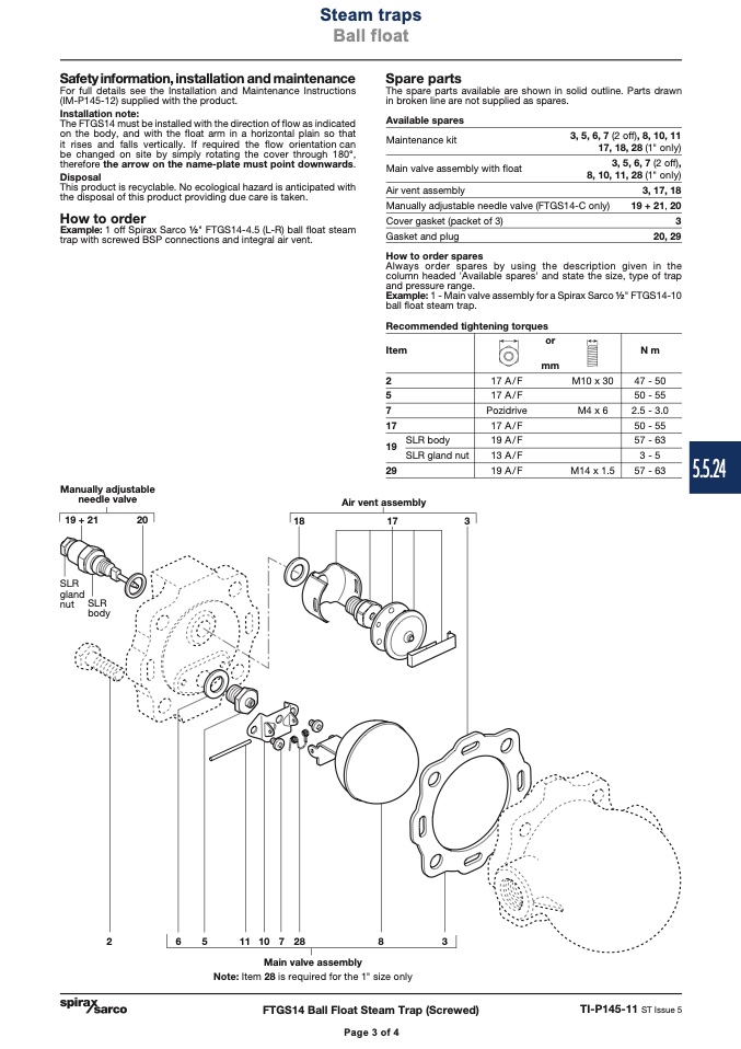
The spare parts available are shown in solid outline. Parts drawn
in broken line are not supplied as spares.
Manually adjustable
needle valve
19 + 21
20
SLR
gland
nut SLR
Air vent assembly
18
17
3
body
2
6
5
1110728
8
3
Main valve assembly
Note: Item 28 is required for the 1" size only
FTGS14 Ball Float Steam Trap (Screwed)
TI-P145-11 ST Issue 5
Steam traps
Ball float
Page 4 of 4
Page 3 of 4
Available spares
Maintenance kit
Main valve assembly with float
3, 5, 6, 7 (2 off), 8, 10, 11
17, 18, 28 (1" only)
3, 5, 6, 7 (2 off),
8, 10, 11, 28 (1" only)
Air vent assembly
Manually adjustable needle valve (FTGS14-C only)
Cover gasket (packet of 3)
Gasket and plug
How to order spares
3, 17, 18
19 + 21, 20
3
20, 29
Always order spares by using the description given in the
column headed 'Available spares' and state the size, type of trap
and pressure range.
Example: 1 - Main valve assembly for a Spirax Sarco 1⁄2" FTGS14-10
ball float steam trap.
Recommended tightening torques
Item
or
mm
N m
47 - 50
50 - 55
2.5 - 3.0
50 - 55
57 - 63
3 -5
57 - 63
2
5
7
17
19
29
SLR body
SLR gland nut
17 A/F
17 A/F
Pozidrive
17 A/F
19 A/F
13 A/F
19 A/F
M10 x 30
M4 x 6
M14 x 1.5
5.5.24

