Steam traps
Ball float
Siz
e
A
A
1
B
C
D
E
F
Weight
Dimensions/weights (approximate) in mm and kg
Screwed/SW Tri-clamp PN16/25 ASME150 ASME300
Withdrawal distance FTS14-C Screwed/SW Flanged
1⁄2"
135
180
-
-
-
9
7
48162
135
3⁄4"
135
180
-
-
-
9
7
48162
135
22
3.75
-
22
3.75
-
22
4.25
-
22
-
5.00
22
-
5.00
22
-
6.25
Flanged DN15, 20 and FTS14-C
1"
139
DN15
-
DN20
-
DN25
-
200
-
-
150
-
150
-
160
-
-
147
194
147
194
160
204
113 51 179
145
97 77 162
135
102 77 162
135
113 62 179
145
Flanged DN25
Screwed, Socket weld and Tri-clamp ends (all sizes)
A
D
A1
D
D
F
B
B
C
E
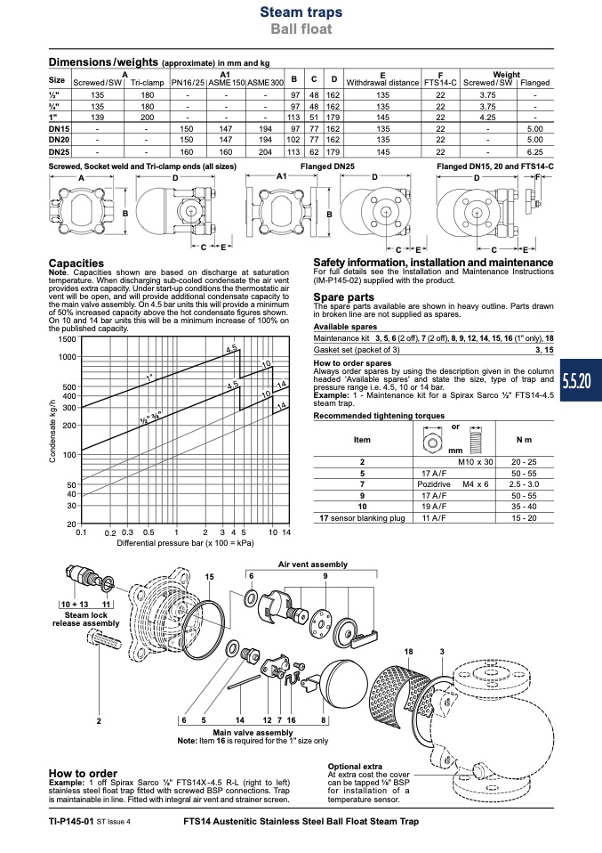
Capacities
Note. Capacities shown are based on discharge at saturation
temperature. When discharging sub-cooled condensate the air vent
provides extra capacity. Under start-up conditions the thermostatic air
vent will be open, and will provide additional condensate capacity to
the main valve assembly. On 4.5 bar units this will provide a minimum
of 50% increased capacity above the hot condensate figures shown.
On 10 and 14 bar units this will be a minimum increase of 100% on
the published capacity.
��������
��������
������
������
������
������
������
����
����
����
����
������
�����������
�
������
��
�
�
������
��������
Differential pressure bar (x 100 = kPa)
C
E
C
E
������
������
����
����
����
����
����
������
����
C
o
n
d
e
n
s
a
t
e
k
g
/
h
10 + 13 11
Steam lock
release assembly
2
18
3
At extra cost the cover
can be tapped " BSP
for installation of a
temperature sensor.
6
5
14
12716
8
Main valve assembly
How to order
Example: 1 off Spirax Sarco 1⁄2" FTS14X-4.5 R-L (right to left)
stainless steel float trap fitted with screwed BSP connections. Trap
is maintainable in line. Fitted with integral air vent and strainer screen.
Air vent assembly
15
6
9
Note: Item 16 is required for the 1" size only
TI-P145-01 ST Issue 4
FTS14 Austenitic Stainless Steel Ball Float Steam Trap
Safety information, installation and maintenance
For full details see the Installation and Maintenance Instructions
(IM-P145-02) supplied with the product.
Spare parts
The spare parts available are shown in heavy outline. Parts drawn
in broken line are not supplied as spares.
Available spares
Maintenance kit 3, 5, 6 (2 off), 7 (2 off), 8, 9, 12, 14, 15, 16 (1" only), 18
Gasket set (packet of 3)
3, 15
Always order spares by using the description given in the column
headed 'Available spares' and state the size, type of trap and
pressure range i.e. 4.5, 10 or 14 bar.
Example: 1 - Maintenance kit for a Spirax Sarco 1⁄2" FTS14-4.5
steam trap.
How to order spares
Recommended tightening torques
Item
or
mm
N m
20 - 25
50 - 55
2.5 - 3.0
50 - 55
35 - 40
15 - 20
2
5
7
9
10
17 sensor blanking plug
17 A/F
Pozidrive
17 A/F
19 A/F
11 A/F
M10 x 30
M4 x 6
Optional extra
5.5.20

