Boiler house
Steam injectors
Safety information, installation and maintenance
Capacity - selecting a steam injector
This document does not contain sufficient information to install the
product safely. See the Installation and Maintenance Instructions
supplied with the product.
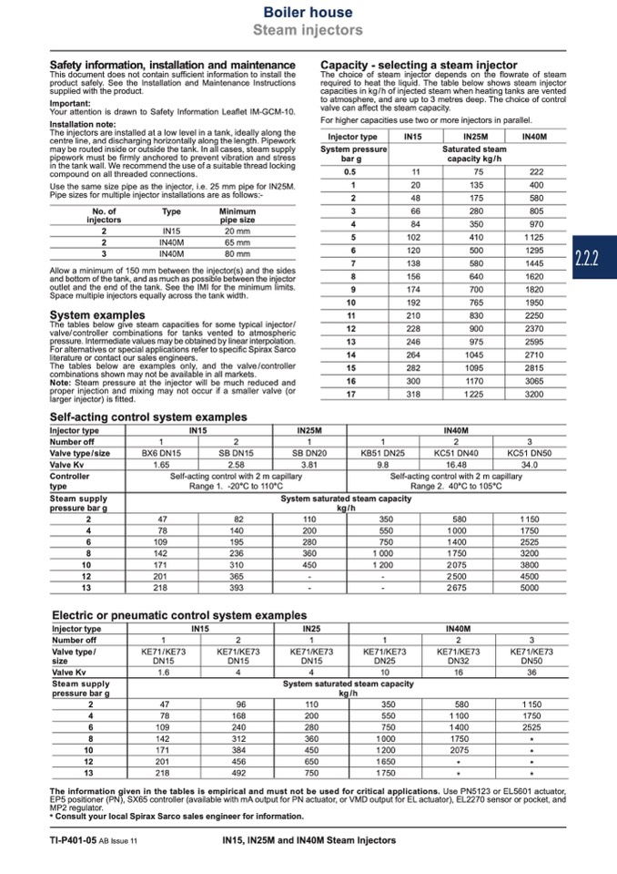
The choice of steam injector depends on the flowrate of steam
required to heat the liquid. The table below shows steam injector
capacities in kg / h of injected steam when heating tanks are vented
to atmosphere, and are up to 3 metres deep. The choice of control
valve can affect the steam capacity.
Important:
Your attention is drawn to Safety Information Leaflet IM-GCM-10.
Installation note:
The injectors are installed at a low level in a tank, ideally along the
centre line, and discharging horizontally along the length. Pipework
may be routed inside or outside the tank. In all cases, steam supply
pipework must be firmly anchored to prevent vibration and stress
in the tank wall. We recommend the use of a suitable thread locking
compound on all threaded connections.
Use the same size pipe as the injector, i.e. 25 mm pipe for IN25M.
Pipe sizes for multiple injector installations are as follows:-
For higher capacities use two or more injectors in parallel.
IN15 IN25M
1
BX6 DN15
1.65
1
KE71 / KE73
DN15
1.6
IN15
IN15
2
SB DN15
2.58
Self-acting control with 2 m capillary
Range 1. -20°C to 110°C
2
KE71/KE73
DN15
4
IN25M
1
SB DN20
3.81
Injector type
System pressure
bar g
0.5
1
2
3
4
Saturated steam
capacity kg/h
IN40M
222
400
580
805
970
11
75
20
135
48
175
66
280
84
350
102
410
120
500
138
580
156
640
174
700
192
765
210
830
228
900
246
975
264
1045
282
1095
300
1170
318
1 225
No. of
Type
injectors
2
IN15
2
IN40M
3
IN40M
Minimum
pipe size
20 mm
65 mm
80 mm
5
1125
6
1295
7
1445
8
1620
9
1820
10
1950
11
2250
12
2370
13
2595
14
2710
15
2815
16
3065
17
3200
Allow a minimum of 150 mm between the injector(s) and the sides
and bottom of the tank, and as much as possible between the injector
outlet and the end of the tank. See the IMI for the minimum limits.
Space multiple injectors equally across the tank width.
The tables below give steam capacities for some typical injector/
valve/controller combinations for tanks vented to atmospheric
pressure. Intermediate values may be obtained by linear interpolation.
For alternatives or special applications refer to specific Spirax Sarco
literature or contact our sales engineers.
Self-acting control system examples
Injector type
Number off
Valve type/size
Valve Kv
Controller
type
Steam supply
pressure bar g
System examples
The tables below are examples only, and the valve/controller
combinations shown may not be available in all markets.
Note: Steam pressure at the injector will be much reduced and
proper injection and mixing may not occur if a smaller valve (or
larger injector) is fitted.
IN40M
3
KC51 DN50
34.0
Self-acting control with 2 m capillary
Range 2. 40°C to 105°C
System saturated steam capacity
kg/h
47
82
110
350
580
78
140
200
550
1 000
109
195
280
750
1 400
142
236
360
1 000
1 750
171
310
450
1 200
2 075
201
365
-
-
2 500
218
393
-
-
2 675
2
1150
4
1750
6
2525
8
3200
10
3800
12
4500
13
5000
Electric or pneumatic control system examples
Injector type
Number off
Valve type/
IN40M
3
KE71/KE73
DN50
36
IN25
1
size
Valve Kv
Steam supply
pressure bar g
System saturated steam capacity
kg/h
KE71/KE73
DN15
4
1
KB51 DN25
9.8
1
KE71/KE73
DN25
10
2
KC51 DN40
16.48
2
KE71/KE73
DN32
16
47
96
110
350
580
78
168
200
550
1 100
109
240
280
750
1 400
142
312
360
1 000
1750
171
384
450
1 200
2075
201
456
650
1 650
*
218
492
750
1 750
*
2
1150
4
1750
6
2525
8
10
12
13
*
*
*
*
The information given in the tables is empirical and must not be used for critical applications. Use PN5123 or EL5601 actuator,
EP5 positioner (PN), SX65 controller (available with mA output for PN actuator, or VMD output for EL actuator), EL2270 sensor or pocket, and
MP2 regulator.
* Consult your local Spirax Sarco sales engineer for information.
TI-P401-05 AB Issue 11
IN15, IN25M and IN40M Steam Injectors
2.2.2

