Boiler house
Feedtank ancillaries
Materials
No. Description
1
Arm body
2
Protector rods
3
Glass tube
4
Gland nut
5
Top plug
6
Plug cock
7
Packing sleeve
8
Packing washer
9
Top plug gasket
10 'C' section protector
11 Plastic tube
12 Tube supports
(used with item 11)
Dimensions (approximate) in millimetres
Material
Weights
Top arm
Intermediate arm
Bottom arm
Glass
Protector rod
'C' section protector
Plastic tube (1100 mm)
85
0.65 kg
0.62 kg
Gunmetal
Brass
Glass
Borosilicate
0.69 kg
0.145 kg / 100 mm length
0.015 kg / 100 mm length
BS 1400 LG2
BS 2874 CZ121
Brass
Brass
Gunmetal
Rubber
Nitrile
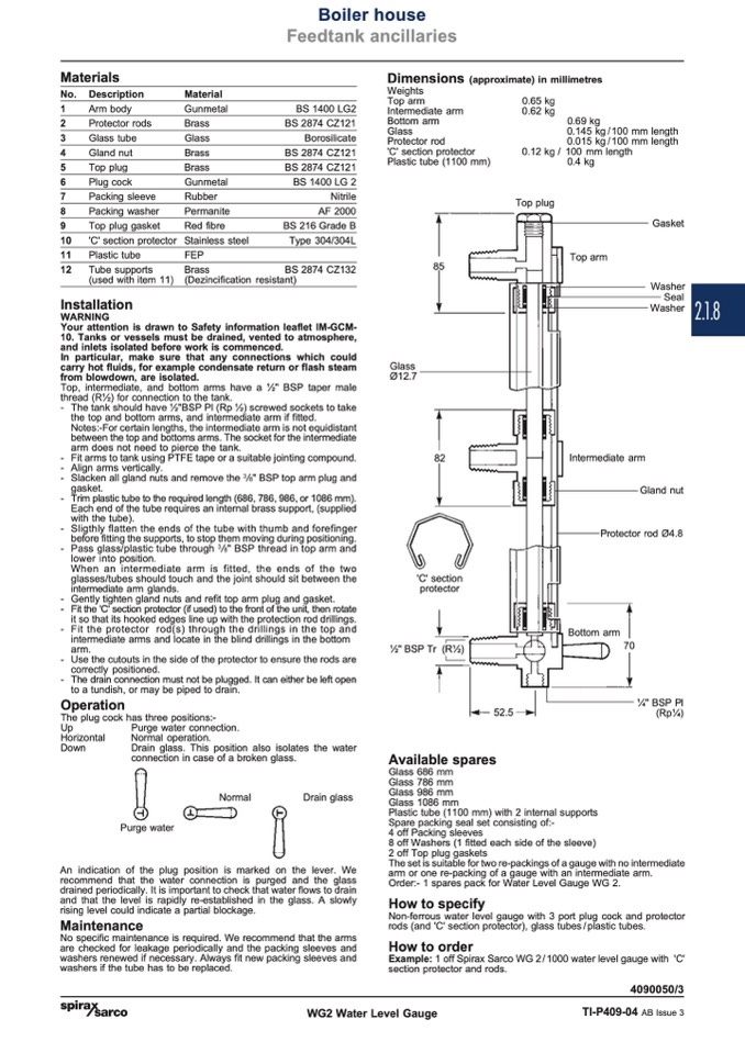
Top plug
Top arm
BS 2874 CZ121
BS 2874 CZ121
BS 1400 LG 2
0.12 kg / 100 mm length
0.4 kg
Permanite
Red fibre
Stainless steel
FEP
AF 2000
BS 216 Grade B
Type 304/304L
Gasket
Washer
Seal
Washer
Brass
(Dezincification resistant)
BS 2874 CZ132
Installation
WARNING
Your attention is drawn to Safety information leaflet IM-GCM-
10. Tanks or vessels must be drained, vented to atmosphere,
and inlets isolated before work is commenced.
In particular, make sure that any connections which could
carry hot fluids, for example condensate return or flash steam
Glass
from blowdown, are isolated.
Ø12.7
Top, intermediate, and bottom arms have a 1⁄2" BSP taper male
thread (R1⁄2) for connection to the tank.
- The tank should have 1⁄2"BSP Pl (Rp 1⁄2) screwed sockets to take
the top and bottom arms, and intermediate arm if fitted.
Notes:-For certain lengths, the intermediate arm is not equidistant
between the top and bottoms arms. The socket for the intermediate
arm does not need to pierce the tank.
- Fit arms to tank using PTFE tape or a suitable jointing compound.
82
- Align arms vertically.
- Slacken all gland nuts and remove the
3
/
8
" BSP top arm plug and
Intermediate arm
Gland nut
Protector rod Ø4.8
Bottom arm
70
gasket.
- Trim plastic tube to the required length (686, 786, 986, or 1086 mm).
Each end of the tube requires an internal brass support, (supplied
with the tube).
- Sligthly flatten the ends of the tube with thumb and forefinger
before fitting the supports, to stop them moving during positioning.
- Pass glass/plastic tube through
3
/
8
" BSP thread in top arm and
lower into position.
When an intermediate arm is fitted, the ends of the two
glasses/tubes should touch and the joint should sit between the
'C' section
intermediate arm glands.
protector
- Gently tighten gland nuts and refit top arm plug and gasket.
- Fit the 'C' section protector (if used) to the front of the unit, then rotate
it so that its hooked edges line up with the protection rod drillings.
- Fit the protector rod(s) through the drillings in the top and
intermediate arms and locate in the blind drillings in the bottom
arm.
1⁄2" BSP Tr (R1⁄2)
- Use the cutouts in the side of the protector to ensure the rods are
correctly positioned.
- The drain connection must not be plugged. It can either be left open
Operation
to a tundish, or may be piped to drain.
1⁄4" BSP Pl
(Rp1⁄4)
The plug cock has three positions:-
52.5
Available spares
Up
Horizontal
Down
Purge water connection.
Normal operation.
Drain glass. This position also isolates the water
connection in case of a broken glass.
Normal
Drain glass
Purge water
An indication of the plug position is marked on the lever. We
recommend that the water connection is purged and the glass
drained periodically. It is important to check that water flows to drain
and that the level is rapidly re-established in the glass. A slowly
rising level could indicate a partial blockage.
Maintenance
No specific maintenance is required. We recommend that the arms
are checked for leakage periodically and the packing sleeves and
washers renewed if necessary. Always fit new packing sleeves and
washers if the tube has to be replaced.
Glass 686 mm
Glass 786 mm
Glass 986 mm
Glass 1086 mm
Plastic tube (1100 mm) with 2 internal supports
Spare packing seal set consisting of:-
4 off Packing sleeves
8 off Washers (1 fitted each side of the sleeve)
2 off Top plug gaskets
The set is suitable for two re-packings of a gauge with no intermediate
arm or one re-packing of a gauge with an intermediate arm.
Order:- 1 spares pack for Water Level Gauge WG 2.
How to specify
Non-ferrous water level gauge with 3 port plug cock and protector
rods (and 'C' section protector), glass tubes / plastic tubes.
How to order
Example: 1 off Spirax Sarco WG 2 / 1000 water level gauge with 'C'
section protector and rods.
4090050/3
WG2 Water Level Gauge
TI-P409-04 AB Issue 3
2.1.8

