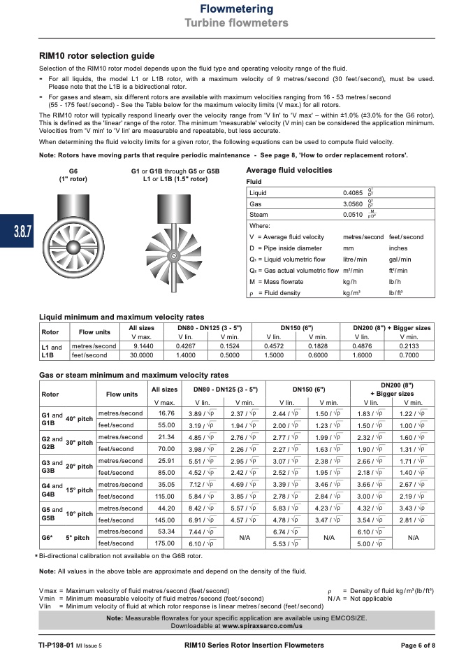
3.8.7
Q1
0.4085
D2
Q2
3.0560
D2
M
0.0510
p
.
D2
metres / second
mm
litre / min
m
2
/min
kg/h
kg/m
3
feet / second
inches
gal / min
ft
2
/ min
lb/h
lb/ft
3
RIM10 rotor selection guide
Liquid minimum and maximum velocity rates
All sizes
DN80 - DN125 (3 - 5")
DN200 (8") + Bigger sizes
Rotor
Flow units
Flowmetering
Turbine flowmeters
Selection of the RIM10 rotor model depends upon the fluid type and operating velocity range of the fluid.
-
For all liquids, the model L1 or L1B rotor, with a maximum velocity of 9 metres/second (30 feet/second), must be used.
Please note that the L1B is a bidirectional rotor.
-
For gases and steam, six different rotors are available with maximum velocities ranging from 16 - 53 metres/second
(55 - 175 feet/second) - See the Table below for the maximum velocity limits (V max.) for all rotors.
The RIM10 rotor will typically respond linearly over the velocity range from 'V lin' to 'V max' – within ±1.0% (±3.0% for the G6 rotor).
This is defined as the 'linear' range of the rotor. The minimum 'measurable' velocity (V min) can be considered the application minimum.
Velocities from 'V min' to 'V lin' are measurable and repeatable, but less accurate.
When determining the fluid velocity limits for a given rotor, the following equations can be used to compute fluid velocity.
Note: Rotors have moving parts that require periodic maintenance - See page 8, 'How to order replacement rotors'.
G6
(1" rotor)
G1 or G1B through G5 or G5B
L1 or L1B (1.5" rotor)
Average fluid velocities
Fluid
Liquid
Gas
Steam
Where:
V = Average fluid velocity
D = Pipe inside diameter
Q
1
= Liquid volumetric flow
Q
2
= Gas actual volumetric flow
M = Mass flowrate
V lin.
V min.
L1B
feet/second
30.0000
1.4000
0.5000
1.5000
0.6000
1.6000
0.7000
V max.
V lin.
V min.
metres/second
9.1440
0.4267
0.1524
0.4572
0.1828
0.4876
0.2133
L1 and
Gas or steam minimum and maximum velocity rates
Rotor
G1 and
G1B
G2 and
G2B
G3 and
G3B
G4 and
G4B
G5 and
G5B
G6*
Flow units
metres /second
feet /second
metres /second
feet /second
metres /second
feet /second
metres /second
feet /second
metres /second
feet /second
metres /second
feet /second
All sizes
V max.
16.76
55.00
21.34
70.00
25.91
85.00
35.05
115.00
44.20
145.00
53.34
175.00
DN80 - DN125 (3 - 5")
DN150 (6")
DN200 (8")
+ Bigger sizes
V lin.
3.89 /
3.19/
4.85 /
3.98 /
5.51 /
4.52 /
7.12 /
5.84 /
8.42 /
6.91 /
7.44/
6.10/
V min.
2.37 /
1.94/
2.76 /
2.26 /
2.95 /
2.42 /
4.69 /
3.85 /
5.57 /
4.57 /
N/A
V lin.
2.44 /
2.00 /
2.77 /
2.27 /
3.07 /
2.52 /
3.39 /
2.78 /
5.83 /
4.78 /
6.74 /
5.53 /
V min.
1.50 /
1.23/
1.99 /
1.63 /
2.38 /
1.95 /
3.46 /
2.84 /
4.23 /
3.47 /
N/A
ρ
Downloadable at www.spiraxsarco.com/us
TI-P198-01 MI Issue 5
RIM10 Series Rotor Insertion Flowmeters
Page 6 of 8
40° pitch
30° pitch
20° pitch
15° pitch
10° pitch
5° pitch
V lin.
1.83 /
1.50 /
2.32 /
1.90/
2.66 /
2.18/
3.66 /
3.00 /
4.32 /
3.54 /
6.10/
5.00 /
V min.
1.22/
1.00/
1.60 /
1.31 /
1.71 /
1.40 /
2.67 /
2.19 /
3.43 /
2.81 /
N/A
* Bi-directional calibration not available on the G6B rotor.
Note: All values in the above table are approximate and depend on the density of the fluid.
Vmax = Maximum velocity of fluid metres/second (feet/second)
V min = Minimum measurable velocity of fluid metres / second (feet / second)
Vlin = Minimum velocity of fluid at which rotor response is linear metres/second (feet/second)
= Density of fluid kg/m
3
(lb/ft
3
)
= Not applicable
N / A
Note: Measurable flowrates for your specific application are available using EMCOSIZE.
ρ
= Fluid density
DN150 (6")
V lin.
V min.

