Boiler house
Heat recovery systems
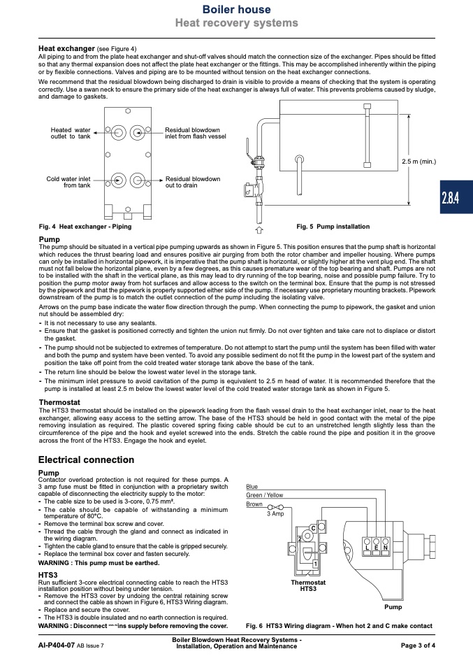
Heat exchanger (see Figure 4)
All piping to and from the plate heat exchanger and shut-off valves should match the connection size of the exchanger. Pipes should be fitted
so that any thermal expansion does not affect the plate heat exchanger or the fittings. This may be accomplished inherently within the piping
or by flexible connections. Valves and piping are to be mounted without tension on the heat exchanger connections.
We recommend that the residual blowdown being discharged to drain is visible to provide a means of checking that the system is operating
correctly. Use a swan neck to ensure the primary side of the heat exchanger is always full of water. This prevents problems caused by sludge,
and damage to gaskets.
Heated water
outlet to tank
Cold water inlet
from tank
Fig. 4 Heat exchanger - Piping
Pump
Residual blowdown
inlet from flash vessel
Residual blowdown
out to drain
2.5 m (min.)
Fig. 5 Pump installation
The pump should be situated in a vertical pipe pumping upwards as shown in Figure 5. This position ensures that the pump shaft is horizontal
which reduces the thrust bearing load and ensures positive air purging from both the rotor chamber and impeller housing. Where pumps
can only be installed in horizontal pipework, it is imperative that the pump shaft is horizontal, or slightly higher at the vent plug end. The shaft
must not fall below the horizontal plane, even by a few degrees, as this causes premature wear of the top bearing and shaft. Pumps are not
to be installed with the shaft in the vertical plane, as this may lead to dry running of the top bearing, noise and possible pump failure. Try to
position the pump motor away from hot surfaces and allow access to the switch on the terminal box. Ensure that the pump is not stressed
by the pipework and that the pipework is properly supported either side of the pump. If necessary use proprietary mounting brackets. Pipework
downstream of the pump is to match the outlet connection of the pump including the isolating valve.
Arrows on the pump base indicate the water flow direction through the pump. When connecting the pump to pipework, the gasket and union
nut should be assembled dry:
- It is not necessary to use any sealants.
- Ensure that the gasket is positioned correctly and tighten the union nut firmly. Do not over tighten and take care not to displace or distort
the gasket.
- The pump should not be subjected to extremes of temperature. Do not attempt to start the pump until the system has been filled with water
and both the pump and system have been vented. To avoid any possible sediment do not fit the pump in the lowest part of the system and
position the take off point from the cold treated water storage tank above the base of the tank.
- The return line should be below the lowest water level in the storage tank.
- The minimum inlet pressure to avoid cavitation of the pump is equivalent to 2.5 m head of water. It is recommended therefore that the
pump is installed at least 2.5 m below the lowest water level of the cold treated water storage tank as shown in Figure 5.
Thermostat
The HTS3 thermostat should be installed on the pipework leading from the flash vessel drain to the heat exchanger inlet, near to the heat
exchanger, allowing easy access to the setting arrow. The base of the HTS3 should be held in good contact with the metal of the pipe
removing insulation as required. The plastic covered spring fixing cable should be cut to an unstretched length slightly less than the
circumference of the pipe and the hook and eyelet screwed into the ends. Stretch the cable round the pipe and position it in the groove
across the front of the HTS3. Engage the hook and eyelet.
Electrical connection
Pump
Contactor overload protection is not required for these pumps. A
3 amp fuse must be fitted in conjunction with a proprietary switch
capable of disconnecting the electricity supply to the motor:
- The cable size to be used is 3-core, 0.75 mm2.
- The cable should be capable of withstanding a minimum
temperature of 80°C.
- Remove the terminal box screw and cover.
- Thread the cable through the gland and connect as indicated in
the wiring diagram.
- Tighten the cable gland to ensure that the cable is gripped securely.
- Replace the terminal box cover and fasten securely.
WARNING : This pump must be earthed.
HTS3
Run sufficient 3-core electrical connecting cable to reach the HTS3
installation position without being under tension.
- Remove the HTS3 cover by undoing the central retaining screw
Thermostat
HTS3
and connect the cable as shown in Figure 6, HTS3 Wiring diagram.
- Replace and secure the cover.
- The HTS3 is double insulated and no earth connection is required.
WARNING : Disconnect mains supply before removing the cover.
Pump
Fig. 6 HTS3 Wiring diagram - When hot 2 and C make contact
Boiler Blowdown Heat Recovery Systems -
AI-P404-07 AB Issue 7
Installation, Operation and Maintenance
Page 3 of 4
2.8.4

