Boiler house
Heat recovery systems
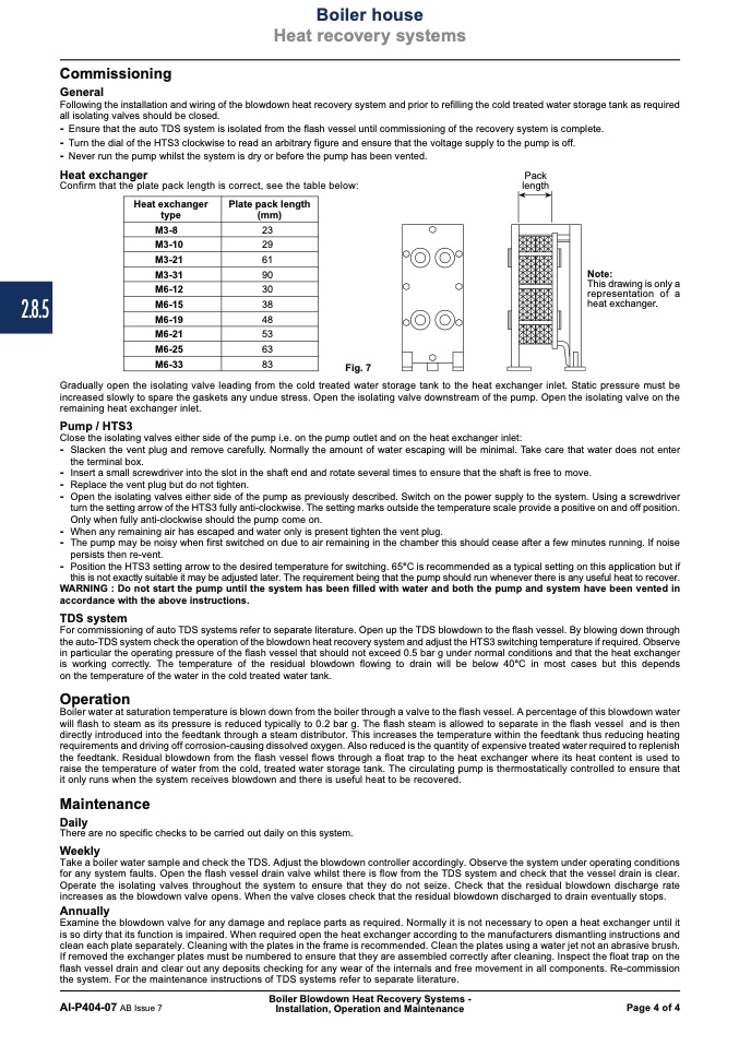
Heat exchanger
type
Plate pack length
(mm)
M3-8
23
M3-10
29
M3-21
61
M3-31
90
M6-12
30
M6-15
38
M6-19
48
M6-21
53
M6-25
63
M6-33
83
2.8.5
Commissioning
General
Following the installation and wiring of the blowdown heat recovery system and prior to refilling the cold treated water storage tank as required
all isolating valves should be closed.
- Ensure that the auto TDS system is isolated from the flash vessel until commissioning of the recovery system is complete.
- Turn the dial of the HTS3 clockwise to read an arbitrary figure and ensure that the voltage supply to the pump is off.
- Never run the pump whilst the system is dry or before the pump has been vented.
Heat exchanger
Pack
Confirm that the plate pack length is correct, see the table below:
length
Note:
This drawing is only a
representation of a
heat exchanger.
Fig. 7
Gradually open the isolating valve leading from the cold treated water storage tank to the heat exchanger inlet. Static pressure must be
increased slowly to spare the gaskets any undue stress. Open the isolating valve downstream of the pump. Open the isolating valve on the
remaining heat exchanger inlet.
Pump / HTS3
Close the isolating valves either side of the pump i.e. on the pump outlet and on the heat exchanger inlet:
- Slacken the vent plug and remove carefully. Normally the amount of water escaping will be minimal. Take care that water does not enter
the terminal box.
- Insert a small screwdriver into the slot in the shaft end and rotate several times to ensure that the shaft is free to move.
- Replace the vent plug but do not tighten.
- Open the isolating valves either side of the pump as previously described. Switch on the power supply to the system. Using a screwdriver
turn the setting arrow of the HTS3 fully anti-clockwise. The setting marks outside the temperature scale provide a positive on and off position.
Only when fully anti-clockwise should the pump come on.
- When any remaining air has escaped and water only is present tighten the vent plug.
- The pump may be noisy when first switched on due to air remaining in the chamber this should cease after a few minutes running. If noise
persists then re-vent.
- Position the HTS3 setting arrow to the desired temperature for switching. 65°C is recommended as a typical setting on this application but if
this is not exactly suitable it may be adjusted later. The requirement being that the pump should run whenever there is any useful heat to recover.
WARNING : Do not start the pump until the system has been filled with water and both the pump and system have been vented in
accordance with the above instructions.
TDS system
For commissioning of auto TDS systems refer to separate literature. Open up the TDS blowdown to the flash vessel. By blowing down through
the auto-TDS system check the operation of the blowdown heat recovery system and adjust the HTS3 switching temperature if required. Observe
in particular the operating pressure of the flash vessel that should not exceed 0.5 bar g under normal conditions and that the heat exchanger
is working correctly. The temperature of the residual blowdown flowing to drain will be below 40°C in most cases but this depends
on the temperature of the water in the cold treated water tank.
Operation
Boiler water at saturation temperature is blown down from the boiler through a valve to the flash vessel. A percentage of this blowdown water
will flash to steam as its pressure is reduced typically to 0.2 bar g. The flash steam is allowed to separate in the flash vessel and is then
directly introduced into the feedtank through a steam distributor. This increases the temperature within the feedtank thus reducing heating
requirements and driving off corrosion-causing dissolved oxygen. Also reduced is the quantity of expensive treated water required to replenish
the feedtank. Residual blowdown from the flash vessel flows through a float trap to the heat exchanger where its heat content is used to
raise the temperature of water from the cold, treated water storage tank. The circulating pump is thermostatically controlled to ensure that
it only runs when the system receives blowdown and there is useful heat to be recovered.
Maintenance
Daily
There are no specific checks to be carried out daily on this system.
Weekly
Take a boiler water sample and check the TDS. Adjust the blowdown controller accordingly. Observe the system under operating conditions
for any system faults. Open the flash vessel drain valve whilst there is flow from the TDS system and check that the vessel drain is clear.
Operate the isolating valves throughout the system to ensure that they do not seize. Check that the residual blowdown discharge rate
increases as the blowdown valve opens. When the valve closes check that the residual blowdown discharged to drain eventually stops.
Annually
Examine the blowdown valve for any damage and replace parts as required. Normally it is not necessary to open a heat exchanger until it
is so dirty that its function is impaired. When required open the heat exchanger according to the manufacturers dismantling instructions and
clean each plate separately. Cleaning with the plates in the frame is recommended. Clean the plates using a water jet not an abrasive brush.
If removed the exchanger plates must be numbered to ensure that they are assembled correctly after cleaning. Inspect the float trap on the
flash vessel drain and clear out any deposits checking for any wear of the internals and free movement in all components. Re-commission
the system. For the maintenance instructions of TDS systems refer to separate literature.
Boiler Blowdown Heat Recovery Systems -
AI-P404-07 AB Issue 7
Installation, Operation and Maintenance
Page 4 of 4

