Boiler house
Heat recovery systems
2.8.3
Safety information
Your attention is drawn to Safety Information sheet IM-GCM-10 as well as to any national or regional regulations concerning boiler blowdown.
In the UK guidance is given in HSE Guidance Note PM60.
General information
This information describes the Spirax Sarco heat recovery system which is designed to recover the heat in discharged boiler water from
automatic TDS control systems, and a proportion of this water in the form of flash steam. The heat recovery system must only be used to
recover heat from the TDS blowdown. There will be another blowdown point on the bottom of the boiler used for the intermittent removal of
precipitates. This should be kept entirely separate from the heat recovery system. Refer to separate literature for system selection details.
This equipment is designed to save energy. All pipework and the flash vessel should be lagged.
Installation
Flash vessel
As water passes through the blowdown valve it is reduced in pressure. Flash steam is formed and the pipework downstream of the valve will
contain a mixture of steam and blowdown water travelling at high velocity. If the pipeline to the flash vessel is too small in diameter the result
may be erosion of the pipework with turbulence and carryover as it enters the flash vessel.
The best arrangement is to increase the size of the pipework after the blowdown valve:
- Install the flash vessel at a high level adjacent but not bolted to the feedtank.
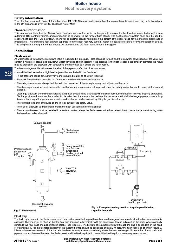
- Fit the pressure gauge set, safety valve and vacuum breaker as shown in Figure 2.
- Pipework from the flash vessel to the feedtank should match the vessel’s vent size.
- The safety valve should always be fitted with the centreline of the spring housing vertically above the valve.
- The discharge pipework must be installed so that undue stresses are not imposed upon the safety valve that could cause distortion and
leakage.
- Discharge pipework should be as short and straight as possible and discharge where it can not cause damage or injury to property or persons.
Discharge pipework must not be smaller in diameter than the valve outlet. Where it is necessary to install discharge pipework over a long
distance lowering of the performance and possible chatter can be avoided by fitting larger diameter pipe.
- There must be no shut-off device on the inlet or outlet of the safety valve.
- The size of pipework to drain should match the flash vessel drain connection size.
- The vacuum breaker must be installed in a vertical position above the flash vessel in the flash steam line to prevent a vacuum forming when
the blowdown valve shuts off.
Vacuum breaker
Pressure gauge,
gauge cock
and
'U' syphon
Flash steam
to feedtank
Safety valve fitted
on a full bore
swept bend.
Discharge piped
to a safe area.
Auto TDS
blowdown
inlet
1 m (max.)
2 m (min.)
Fig. 2 Flash vessel
Float trap
Residual blowdown
to drain
Drain valve
piped to open drain
Fig. 3 Example showing two float traps in parallel when
capacity demands
The build up of water in the flash vessel must be avoided so a float trap with continuous drainage of condensate at saturation temperature is
essential. The trap must be fitted so that the float arm rises and falls vertically with the direction of flow as indicated on the body. Where capacity
demands two float traps should be fitted in parallel (see Figure 3). The flowrate of residual blowdown through the trap is dependent on the head
of water above it. For the full rated capacity of the system the trap should be positioned at least 2 m below the flash vessel as shown in Figure 3.
It is usually most convenient to fit the trap at a low level for easy access immediately above the heat exchanger. No more than 1 m of horizontal
pipework should be used between the flash vessel and the float trap inlet to prevent the float trap from becoming steam locked.
Boiler Blowdown Heat Recovery Systems -
AI-P404-07 AB Issue 7
Installation, Operation and Maintenance
Page 2 of 4

