Optional
drain valve
(closed)
Fig. 1
*
*
Residual blowdown to
Boiler house
Boiler Blowdown Heat Recovery Systems -
Installation, Operation and Maintenance
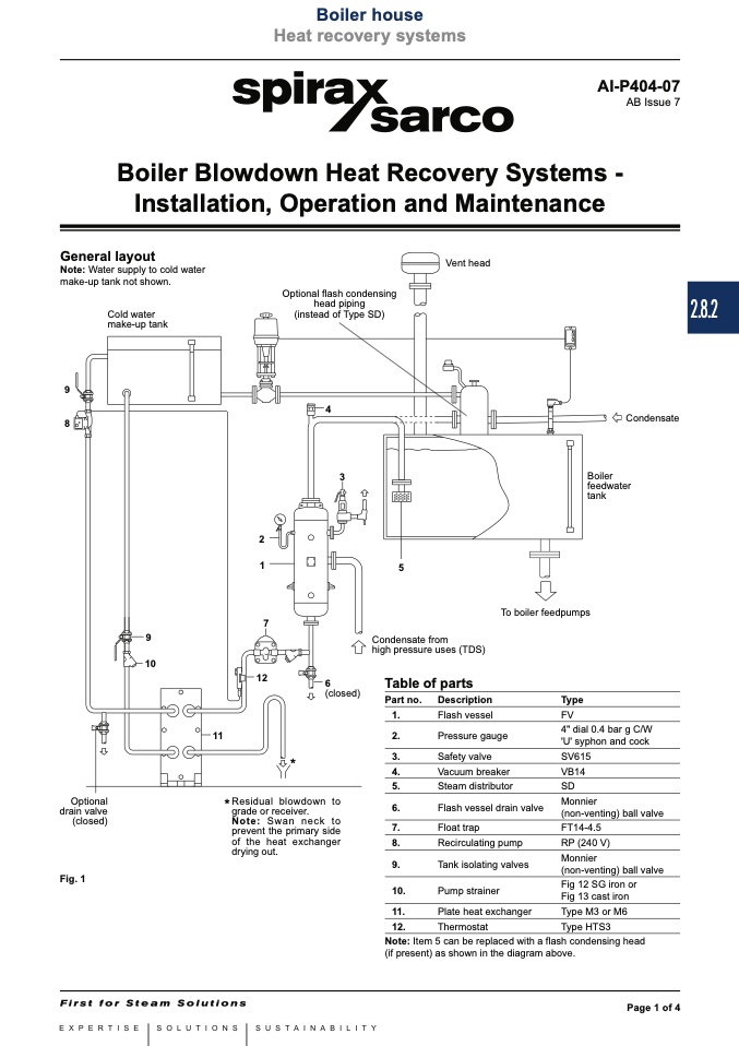
General layout
Note: Water supply to cold water
make-up tank not shown.
Cold water
make-up tank
Vent head
9
8
4
9
10
Condensate from
high pressure uses (TDS)
Table of parts
11
2
1
7
12
5
Heat recovery systems
Local regulations may restrict the use of this product to below the conditions quoted.
In the interests of development and improvement of the product, we reserve the right to change the specification without notice.
© Copyright 2014
Optional flash condensing
head piping
(instead of Type SD)
2.8.2
Condensate
Boiler
feedwater
tank
grade or receiver.
Note: Swan neck to
prevent the primary side
of the heat exchanger
drying out.
3
6
(closed)
Part no.
1.
2.
3.
4.
5.
6.
7.
8.
9.
10.
11.
12.
Description
Flash vessel
Pressure gauge
Safety valve
Vacuum breaker
Steam distributor
Flash vessel drain valve
Float trap
Recirculating pump
Tank isolating valves
Pump strainer
Plate heat exchanger
Thermostat
Type
FV
4" dial 0.4 bar g C/W
'U' syphon and cock
SV615
VB14
SD
Monnier
(non-venting) ball valve
FT14-4.5
RP (240 V)
Monnier
(non-venting) ball valve
Fig 12 SG iron or
Fig 13 cast iron
Type M3 or M6
Type HTS3
To boiler feedpumps
Note: Item 5 can be replaced with a flash condensing head
(if present) as shown in the diagram above.
AI-P404-07
AB Issue 7
Page 1 of 4

