Pipeline ancillaries
Separators and insulation jackets
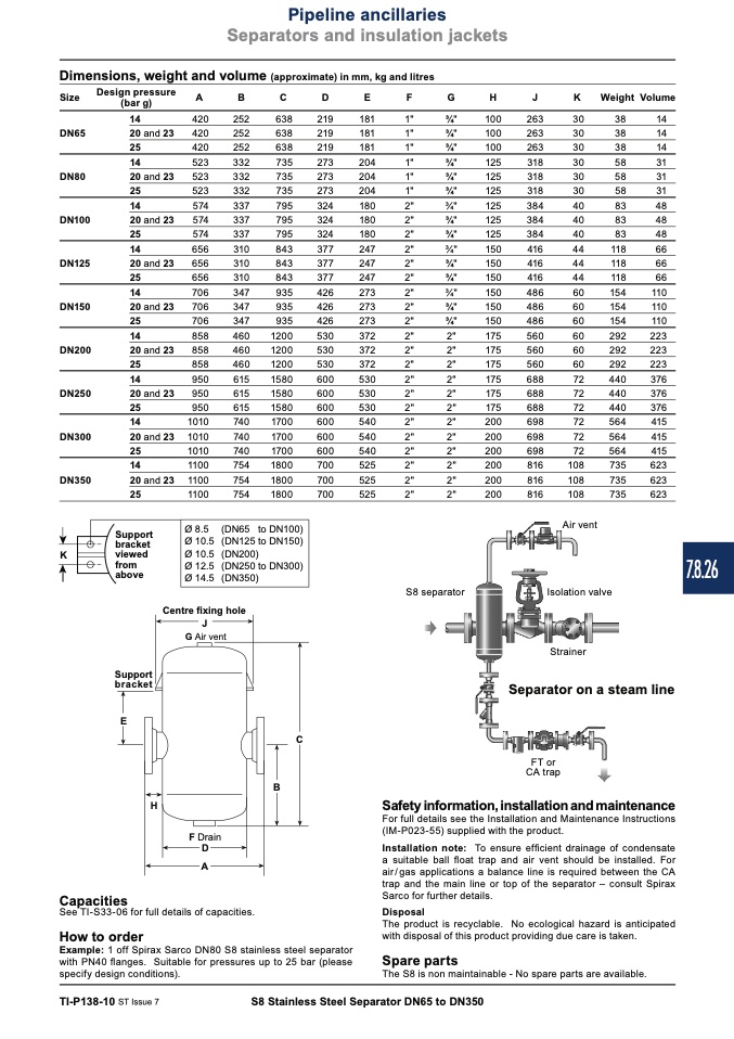
Dimensions, weight and volume (approximate) in mm, kg and litres
Size
Designpressure
(bar g)
14
DN65
20
25
14
DN80
20
25
14
DN100
20
25
14
DN125
20
25
14
DN150
20
25
14
DN200
20
25
14
DN250
20
25
14
DN300
20
25
14
DN350
20
25
A
B
420
252
420
252
420
252
523
332
523
332
523
332
574
337
574
337
574
337
656
310
656
310
656
310
706
347
706
347
706
347
858
460
858
460
858
460
950
615
950
615
950
615
1010
740
1010
740
1010
740
1100
754
1100
754
1100
754
Centre fixing hole
J
G Air vent
C
638
638
638
735
735
735
795
795
795
843
843
843
935
935
935
1200
1200
1200
1580
1580
1580
1700
1700
1700
1800
1800
1800
D
E
219
181
219
181
219
181
273
204
273
204
273
204
324
180
324
180
324
180
377
247
377
247
377
247
426
273
426
273
426
273
530
372
530
372
530
372
600
530
600
530
600
530
600
540
600
540
600
540
700
525
700
525
700
525
F
G
1"
3⁄4"
1"
3⁄4"
1"
3⁄4"
1"
3⁄4"
1"
3⁄4"
1"
3⁄4"
2"
3⁄4"
2"
3⁄4"
2"
3⁄4"
2"
3⁄4"
2"
3⁄4"
2"
3⁄4"
2"
3⁄4"
2"
3⁄4"
2"
3⁄4"
2"
2"
2"
2"
2"
2"
2"
2"
2"
2"
2"
2"
2"
2"
2"
2"
2"
2"
2"
2"
2"
2"
2"
2"
S8 separator
H
J
100
263
100
263
100
263
125
318
125
318
125
318
125
384
125
384
125
384
150
416
150
416
150
416
150
486
150
486
150
486
175
560
175
560
175
560
175
688
175
688
175
688
200
698
200
698
200
698
200
816
200
816
200
816
K
Weight Volume
30
38
14
30
38
14
30
38
14
30
58
31
30
58
31
30
58
31
40
83
48
40
83
48
40
83
48
44
118
66
44
118
66
44
118
66
60
154
110
60
154
110
60
154
110
60
292
223
60
292
223
60
292
223
72
440
376
72
440
376
72
440
376
72
564
415
72
564
415
72
564
415
108
735
623
108
735
623
108
735
623
Air vent
Isolation valve
Strainer
and 23
and 23
and 23
and 23
and 23
and 23
and 23
and 23
and 23
bracket
K
viewed
Support
bracket
E
Support
Ø 8.5
Ø 10.5
Ø 10.5
Ø 12.5
Ø 14.5
(DN65 to DN100)
(DN125 to DN150)
(DN200)
(DN250 to DN300)
(DN350)
from
above
C
B
Separator on a steam line
FT or
CA trap
H
Safety information, installation and maintenance
For full details see the Installation and Maintenance Instructions
(IM-P023-55) supplied with the product.
Installation note: To ensure efficient drainage of condensate
a suitable ball float trap and air vent should be installed. For
air/gas applications a balance line is required between the CA
trap and the main line or top of the separator – consult Spirax
Sarco for further details.
Disposal
The product is recyclable. No ecological hazard is anticipated
with disposal of this product providing due care is taken.
Spare parts
F Drain
D
A
Capacities
See TI-S33-06 for full details of capacities.
How to order
Example: 1 off Spirax Sarco DN80 S8 stainless steel separator
with PN40 flanges. Suitable for pressures up to 25 bar (please
specify design conditions).
The S8 is non maintainable - No spare parts are available.
TI-P138-10 ST Issue 7
S8 Stainless Steel Separator DN65 to DN350
7.8.26

