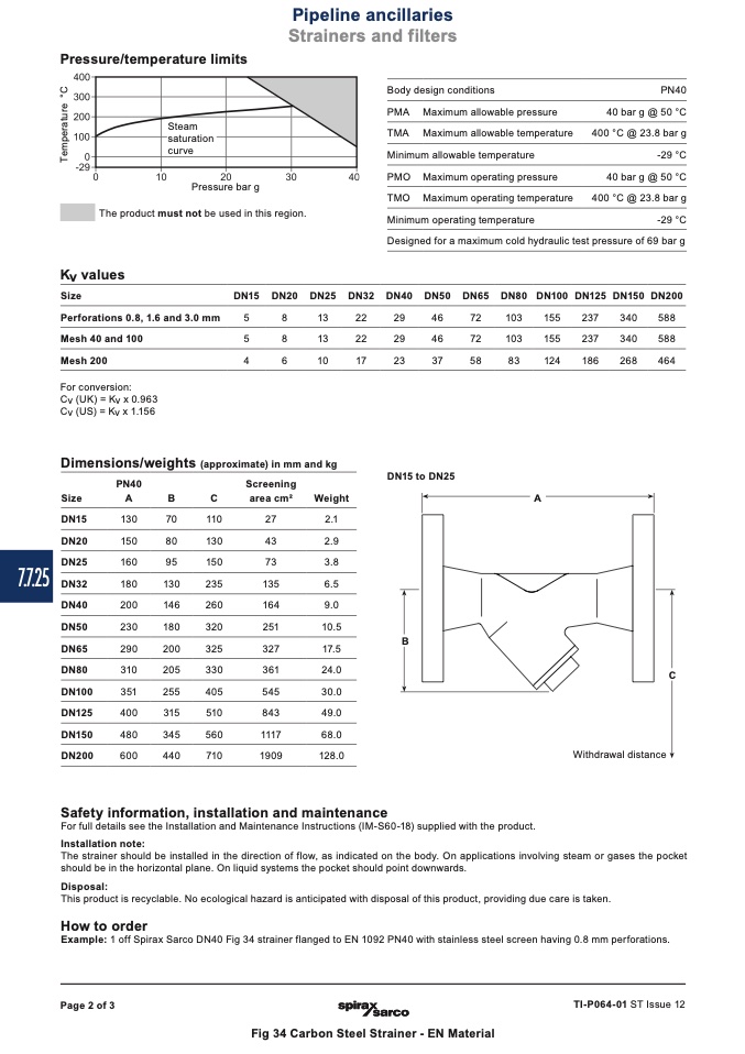
Steam
saturation
Pipeline ancillaries
Strainers and filters
curve
A
7.7.25
B
C
Pressure/temperature limits
Pressure bar g
The product must not be used in this region.
Body design conditions
PMA Maximum allowable pressure
TMA Maximum allowable temperature
Minimum allowable temperature
PMO Maximum operating pressure
TMO Maximum operating temperature
Minimum operating temperature
PN40
40 bar g @ 50 °C
400 °C @ 23.8 bar g
-29 °C
40 bar g @ 50 °C
400 °C @ 23.8 bar g
-29 °C
Kv values
Size
Perforations 0.8, 1.6 and 3.0 mm
Mesh 40 and 100
Mesh200
For conversion:
Cv (UK) = Kv x 0.963
Cv (US) = Kv x 1.156
Dimensions/weights (approximate) in mm and kg
DN15 to DN25
Designed for a maximum cold hydraulic test pressure of 69 bar g
DN15 DN20 DN25 DN32 DN40 DN50 DN65 DN80 DN100 DN125 DN150 DN200
5
8
13
22
29
46
72
103
155
237
340
588
5
8
13
22
29
46
72
103
155
237
340
588
4
6
10
17
23
37
58
83
124
186
268
464
PN40
Screening
Size
A
B
C
area cm2
Weight
DN15
130
DN20
150
DN25
160
DN32
180
DN40
200
DN50
230
DN65
290
DN80
310
DN100
351
DN125
400
DN150
480
DN200
600
70
110
80
130
95
150
130
235
146
260
180
320
200
325
205
330
255
405
315
510
345
560
440
710
27
2.1
43
2.9
73
3.8
135
6.5
164
9.0
251
10.5
327
17.5
361
24.0
545
30.0
843
49.0
1117
68.0
1909
128.0
Withdrawal distance
Safety information, installation and maintenance
For full details see the Installation and Maintenance Instructions (IM-S60-18) supplied with the product.
Installation note:
The strainer should be installed in the direction of flow, as indicated on the body. On applications involving steam or gases the pocket
should be in the horizontal plane. On liquid systems the pocket should point downwards.
Disposal:
This product is recyclable. No ecological hazard is anticipated with disposal of this product, providing due care is taken.
How to order
Example: 1 off Spirax Sarco DN40 Fig 34 strainer flanged to EN 1092 PN40 with stainless steel screen having 0.8 mm perforations.
Page 2 of 3
TI-P064-01 ST Issue 12
Fig 34 Carbon Steel Strainer - EN Material
T
e
m
p
e
r
a
t
u
r
e
°
C

