3.7 ELECTRICAL CONNECTION
S
3.7.1 WIRING DIAGRA
M
Indoor air circuit coil fan DC moto
r
Board cooling fan DC motor
Condensate ejector DC motor
Inlet room air temperature prob
e
Internal air exchange coil temperature prob
e
R
E
C
E
I
V
E
R
D
I
S
P
L
A
Y
&
Motorised condensate
drain damper
Internal outlet air temperature prob
e
External outlet air temperature probe
Deflector stopper
motor
External inlet air temperature probe
External air exchange coil temperature probe
Remote bus contro
l
(optional)
Condensate tray float switc
h
EE valv
e
Power supply socke
t
4-way valve*
External air circui
t
coil fan DC Moto
r
*Only for 10,000 and 12,000 model
s
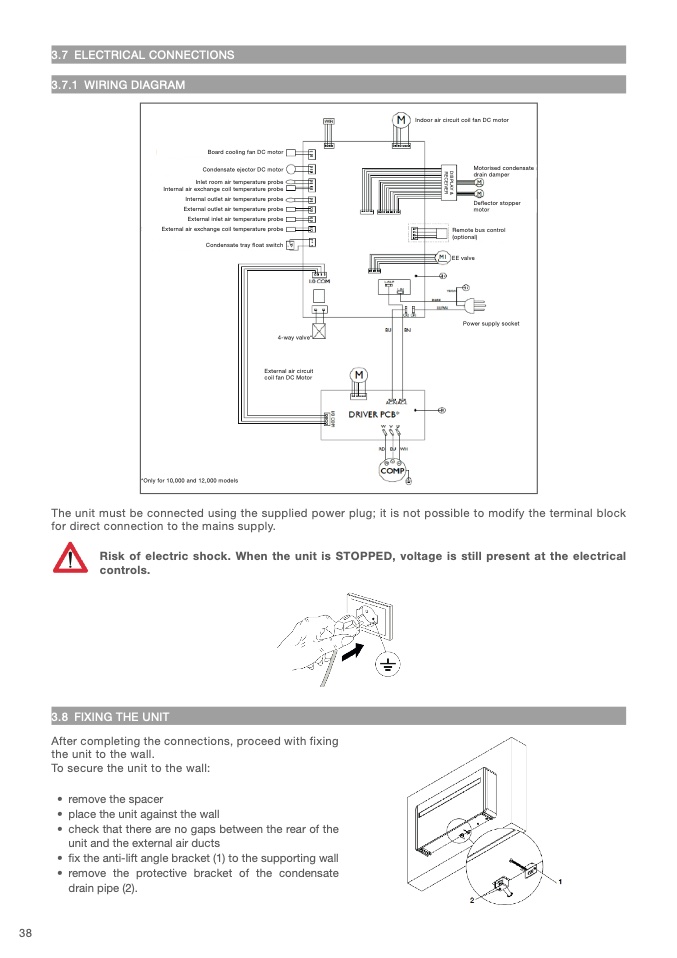
The unit must be connected using the supplied power plug; it is not possible to modify the terminal block
for direct connection to the mains supply
.
Risk of electric shock. When the unit is STOPPED, voltage is still present at the electrica
l
controls
.
3.8 FIXING THE UNI
T
After completing the connections, proceed with fixin
g
the unit to the wall
.
To secure the unit to the wall
:
• remove the space
r
• place the unit against the wall
• check that there are no gaps between the rear of the
unit and the external air duct
s
• fi x the anti-lift angle bracket (1) to the supporting wall
• remove the protective bracket of the condensate
drain pipe (2)
.
38

