3.1.0.3 MINIMUM CLEARANCES FROM OBJECTS AND OTHER UNITS
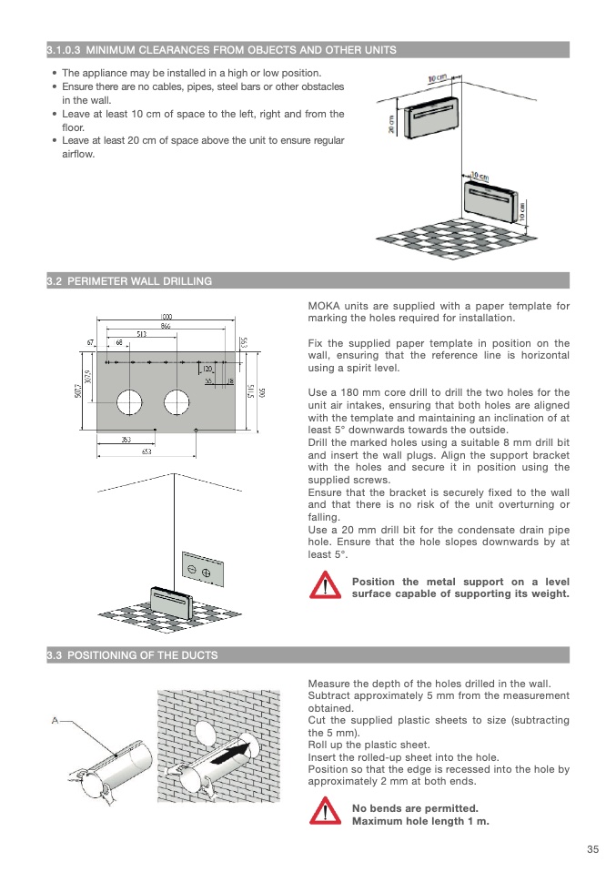
• The appliance may be installed in a high or low position.
• Ensure there are no cables, pipes, steel bars or other obstacles
in the wall
.
• Leave at least 10 cm of space to the left, right and from the
fl oor
.
• Leave at least 20 cm of space above the unit to ensure regular
air
fl ow
.
3.2 PERIMETER WALL DRILLING
MOKA units are supplied with a paper template fo
r
marking the holes required for installation
.
Fix the supplied paper template in position on th
e
wall, ensuring that the reference line is horizonta
l
using a spirit level.
Use a 180 mm core drill to drill the two holes for the
unit air intakes, ensuring that both holes are aligned
with the template and maintaining an inclination of a
t
least 5° downwards towards the outside.
Drill the marked holes using a suitable 8 mm drill bi
t
and insert the wall plugs. Align the support bracket
with the holes and secure it in position using th
e
supplied screws.
Ensure that the bracket is securely fixed to the wall
and that there is no risk of the unit overturning o
r
falling
.
Use a 20 mm drill bit for the condensate drain pipe
hole. Ensure that the hole slopes downwards by a
t
least 5°.
Position the metal support on a level
surface capable of supporting its weight
.
3.3 POSITIONING OF THE DUCTS
Measure the depth of the holes drilled in the wall
.
Subtract approximately 5 mm from the measuremen
t
obtained
.
Cut the supplied plastic sheets to size (subtractin
g
the 5 mm)
.
Roll up the plastic sheet
.
Insert the rolled-up sheet into the hole
.
Position so that the edge is recessed into the hole by
approximately 2 mm at both ends
.
No bends are permitted
.
Maximum hole length 1 m.
35

