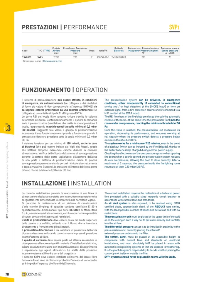
PRESTAZIONI | PERFORMANCE
SVP1
1SV0001
SVP1
2.700
270
2
230/50-60-1 2x(12V-28A/h)
273
75
Dimensioni in mm | Dimensions in mm
FUNZIONAMENTO | OPERATION
Code
TIPO | TYPE
Portata
Airflow
max
Pressione - Prevalenza
Pressure
max
Imax
V/Hz/Ph
Batterie
Batteries
Potenza max Pressurizzatore
Max power Pressurizing unit
W
Pressione sonora
Sound pressure
Lp - dB(A)
Il sistema di pressurizzazione può essere attivato, in condizioni
di emergenza, sia autonomamente (se collegato a dei rivelatori
di fumo e/o calore di tipo convenzionale all’ingresso SMOKE) sia
da segnale esterno proveniente da una centrale antincendio (se
collegato ad un contatto di tipo N.C. all’ingresso EXT.A).
Le porte REI del locale filtro vengono chiuse tramite lo sblocco
automatico dei fermi. Contemporaneamente il quadro di comando
sez.
avvia il pressurizzatore (ventilatore) che mette in sovrappressione il
The pressurisation system can be activated, in emergency
conditions, either independently (if connected to conventional
smoke and / or heat detectors at the SMOKE input) or from an
external signal from a fire protection control unit (if connected to a
N.C. contact at the EXT.A input).
The REI fire doors of the fire lobby are closed through the automatic
release of the locks. At the same time the pressurizer (fan) puts the
room under overpressure, reaching the minimum threshold of 30
Pa.
Once this value is reached, the pressurisation unit modulates its
operation, decreasing its performance, and resumes working at
full capacity when the pressure switch detects a pressure below
minimum threshold of 30 Pa.
The system works for a minimum of 120 minutes, even in the event
of a blackout (which can be induced by the Fire Brigade), thanks to
the buffer batteries kept charged during normal power supply.
Checking the effectiveness of the overpressure system when opening
fire doors: when a door is opened, the pressurisation system reduces
its own overpressure, allowing the door to close correctly. After a
maximum of 2 seconds, the pressure inside the firefighting room
returns to at least 0.30 mbar (30 Pa).
1
.3
locale, raggiungendo in pochi secondi la soglia minima di 0,3 mbar
(30 pascal). Raggiunto tale valore il gruppo di pressurizzazione
interrompe il suo funzionamento e riprende a funzionare quando il
pressostato rileva una pressione sotto la soglia minima di 0,3 mbar
(30 Pa).
Il sistema funziona per un minimo di 120 minuti, anche in caso
di blackout (che può essere indotto dai Vigili del Fuoco), grazie
alle batterie tampone mantenute cariche durante la normale
alimentazione. Verifica dell’efficacia del sistema di sovrappressione
durante l’apertura delle porte tagliafuoco: all’apertura dell’anta
di una porta il sistema di pressurizzazione riduce la propria
sovrappressione permettendo alla porta di richiudersi correttamente
e dopo al massimo 2 secondi, la pressione all’interno del filtro a prova
di fumo ritorna ad almeno 0,30 mbar (30 Pa).
70
INSTALLAZIONE | INSTALLATION
La corretta installazione prevede la realizzazione di una linea di
alimentazione dedicata e protetta con interruttore magnetotermico
adeguatamente dimensionato in conformità alle normative vigenti.
Si prescrive la realizzazione di un sistema di canalizzazioni
d’aria tramite l’impiego di apposite condotte certificate EI120 e
opportunamente dimensionate tipo serie REIDUCT di Maico Italia
S.p.A., a sezione quadrata o circolare, con il minore numero possibile
di curve, deviazioni e l’assenza di restrizioni.
L’unità di pressurizzazione deve essere posta nel limite superiore
della parete o a soffitto, evitando che il flusso d’aria investisca
direttamente e frontalmente gli utilizzatori.
Il pressostato differenziale è da installare in prossimità dell’unità
di pressurizzazione collocando correttamente le prese di pressione
interne/esterne al filtro.
Il quadro di comando deve essere posto ad altezza accessibile in
ottemperanza alle norme vigenti in materia d’installazioni elettriche,
evitare assolutamente zone con impianti automatici di spegnimento
o esposizione agli agenti atmosferici. La scelta della posizione
interna o esterna al filtro è a cura del progettista.
Il sistema SVP1 deve essere installato all’interno del locale filtro
fumo o in locali dove si ritiene improbabile l’innesco di un incendio
ed è impedito l’ingresso di effluenti dell’incendio.
The correct installation requires the realisation of a dedicated power
line protected with a suitably sized magnetic circuit breaker in
accordance with current laws and standards.
An air duct system is also required, to be realised using EI120
certified ducts, appropriately sized, of the REIDUCT type series,
with the least possible number of bends and deviations and with no
restrictions.
The pressurisation unit must be placed at the upper limit of the wall
or on the ceiling in such a way not to put users directly and frontally
into the airflow.
The differential pressure sensor is to be installed in proximity to the
pressurisation unit, correctly placing the internal/
external pressure outlets onto the filter.
The control panel must be placed at an accessible height in
compliance with current laws and standards on electrical
installations, and must absolutely NOT be placed in areas with
automatic extinguishing systems or that are exposed to weathering.
It is the plant designer’s responsibility to decide whether placing the
control panel inside or outside the filte.
SVP1 systems should never be placed in rooms with fire loads.
S
V
P
1
p
r
o
s
s
u
r
i
z
z
a
t
o
r
i
f
i
l
t
r
i
f
u
m
o
|
p
r
e
s
s
u
r
i
z
a
t
i
o
n
f
o
r
f
i
g
h
t
i
n
g
l
o
b
b
i
e
s

