Installation instructions
BGT 1.706
BIOFLEX Pipe system
Installation instructions Fermenter
End connector with graphite sealing ring for corrugated pipe DN 50
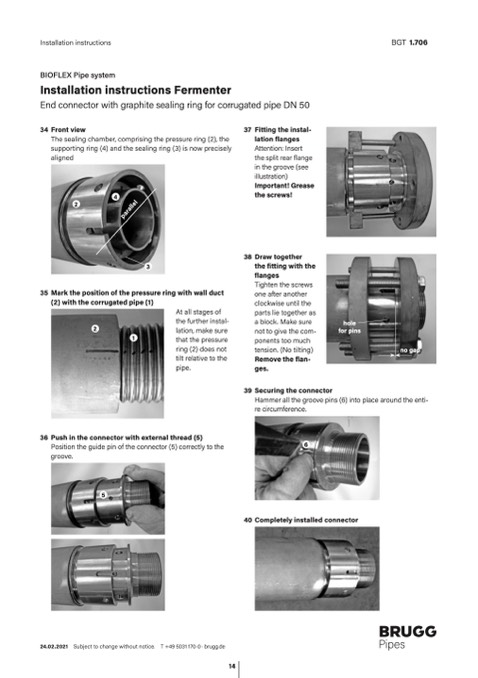
34 Front view
The sealing chamber, comprising the pressure ring (2), the
supporting ring (4) and the sealing ring (3) is now precisely
aligned
4
2
3
35 Mark the position of the pressure ring with wall duct
(2) with the corrugated pipe (1)
37
Fitting the instal-
lation flanges
Attention: Insert
the split rear flange
in the groove (see
illustration)
Important! Grease
the screws!
Draw together
the fitting with the
flanges
Tighten the screws
one after another
clockwise until the
parts lie together as
a block. Make sure
not to give the com-
ponents too much
tension. (No tilting)
Remove the flan-
ges.
2
1
At all stages of
the further instal-
lation, make sure
that the pressure
ring (2) does not
tilt relative to the
pipe.
hole
for pins
36 Push in the connector with external thread (5)
Position the guide pin of the connector (5) correctly to the
groove.
5
Hammer all the groove pins (6) into place around the enti-
re circumference.
6
40 Completely installed connector
24.02.2021 Subject to change without notice. T +49 5031 170-0 · brugg.de
14
38
39 Securing the connector
no gap
parallel
Page 7

