Steam traps
Ball float
Steam
saturation
curve
C
5.5.73
Sizes and pipe connections
DN15, DN20, DN25, DN40 and DN50.
Note: Flow direction when facing the body: - DN15 to DN25 is left to
right. - DN40 and DN50 is right to left.
Standard flanges are EN 1092 PN40 with face-to-face dimensions
in accordance with EN 26554 (Series 1).
On request - ASME (ANSI) B 16.5 Class 150 and 300 flanges are
available with face-to-face dimensions in accordance with EN 26554
(Series 1).
Note: ASME (ANSI) flanges are supplied with tapped (UNC) holes for
flange bolts.
Materials
No. Part
1 Body
2
Cover studs
Cover nuts
3 Cover gasket
4 Cover
Material
Austenitic
stainless steel
(316)
1.4408 / CF8M
Austenitic stainless steel
A2.70
Austenitic stainless steel
A4
Reinforced exfoliated graphite
Austenitic
stainless steel
(316)
1.4408 / CF8M
BS 970 431 S29
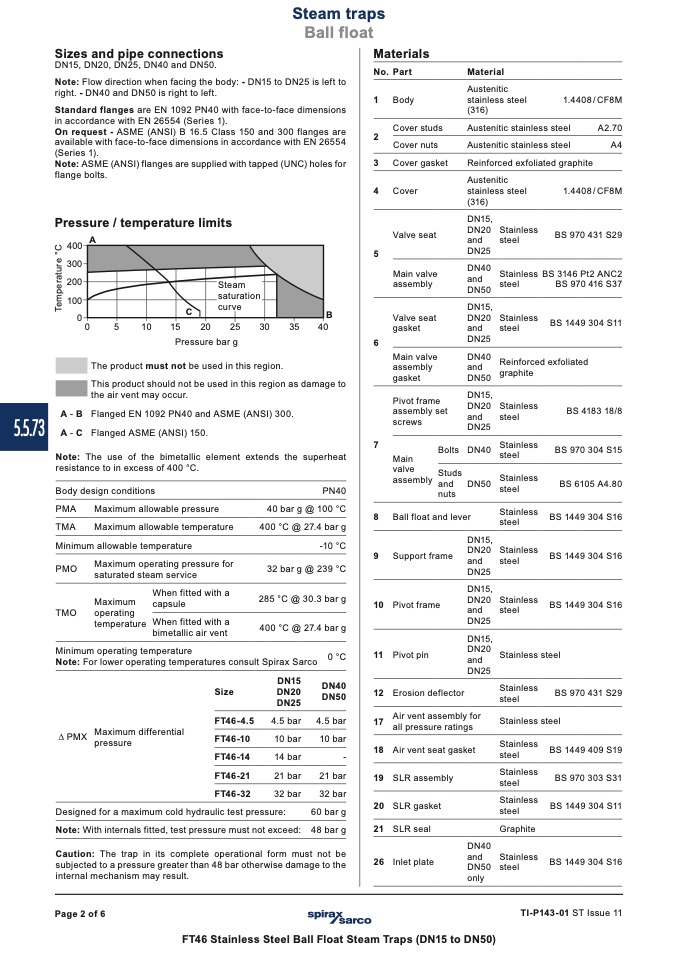
Pressure / temperature limits
DN15,
Valve seat
DN20 Stainless
and
steel
5
DN25
������
������
������
������
��
A-B
A-C
A
Main valve
DN40
Stainless BS 3146 Pt2 ANC2
B
assembly
and
steel
DN50
DN15,
Valve seat
DN20 Stainless
gasket
and
steel
DN25
BS 970 416 S37
BS 1449 304 S11
��
��
����
����
����
����
����
����
����
Pressure bar g
The product must not be used in this region.
This product should not be used in this region as damage to
the air vent may occur.
Flanged EN 1092 PN40 and ASME (ANSI) 300.
Flanged ASME (ANSI) 150.
6
Main valve
DN40
Reinforced exfoliated
assembly
and
graphite
gasket
DN50
Pivot frame
DN15,
assembly set
DN20 Stainless
screws
and
steel
DN25
BS 4183 18/8
BS 970 304 S15
BS 6105 A4.80
BS 1449 304 S16
BS 1449 304 S16
BS 1449 304 S16
steel
BS 970 431 S29
steel
BS 1449 409 S19
BS 970 303 S31
BS 1449 304 S11
BS 1449 304 S16
Note: The use of the bimetallic element extends the superheat
resistance to in excess of 400 °C.
7
Bolts DN40
Stainless
Main
steel
valve
Studs
Stainless
assembly and DN50
steel
nuts
8 Ball float and lever
Stainless
steel
DN15,
9 Support frame
DN20 Stainless
and
steel
DN25
DN15,
10 Pivot frame
DN20 Stainless
and
steel
DN25
DN15,
11 Pivot pin
DN20
Stainless
and
DN25
12 Erosion deflector
Stainless
steel
17
Air vent assembly for
Stainless
all pressure ratings
18 Air vent seat gasket
Stainless
steel
19 SLR assembly
Stainless
steel
20 SLR gasket
Stainless
steel
21 SLR seal
Graphite
Body design conditions
PMA
Maximum allowable pressure
TMA
Maximum allowable temperature
Minimum allowable temperature
PMO
Maximum operating pressure for
saturated steam service
PN40
40 bar g @ 100 °C
400 °C @ 27.4 bar g
-10 °C
32 bar g @ 239 °C
285 °C @ 30.3 bar g
400 °C @ 27.4 bar g
When fitted with a
Maximum
capsule
TMO
operating
temperature When fitted with a
bimetallic air vent
Minimum operating temperature
Note: For lower operating temperatures consult Spirax Sarco
DN15
Size
DN20
DN25
FT46-4.5
4.5 bar
FT46-10
10 bar
FT46-14
14 bar
FT46-21
21 bar
FT46-32
32 bar
PMX
Maximum differential
pressure
0 °C
DN40
DN50
4.5 bar
10 bar
-
21 bar
32 bar
60barg
48barg
Designed for a maximum cold hydraulic test pressure:
Note: With internals fitted, test pressure must not exceed:
Caution: The trap in its complete operational form must not be
subjected to a pressure greater than 48 bar otherwise damage to the
internal mechanism may result.
26 Inlet plate
DN40
and
Stainless
DN50 steel
only
Page 2 of 6
TI-P143-01 ST Issue 11
FT46 Stainless Steel Ball Float Steam Traps (DN15 to DN50)
T
e
m
p
e
r
a
t
u
r
e
°
C

