Dimensions/weights (approximate) in mm and kg
Siz
e
A
B
B
1
C
D
E
F
G
Weight
Safety information, installation and maintenance
For full details see the Installation and Maintenance Instructions
(IM-P145-12) supplied with the product.
Installation note - The IFTGS14 is supplied with a blanking plug in
the sensor adaptor: The sensor is to be fitted on site.
The IFTGS14 must be installed with the direction of flow as indicated
on the cover, and with the float arm in a horizontal plain so that it
rises and falls vertically. The IFTGS14 has been designed for use
in a right to left flow direction when viewed from the name-plate
end, however, it can also be installed in a left to right orientation,
by simply rotating the complete trap through 180°. Caution: Ensure
that adequate distance is allowed for removal of the body and
internals in the event of maintenance. See 'Dimensions/weights'
for withdrawal distances.
Disposal - This product is recyclable. No ecological hazard is
anticipated with the disposal of this product providing due care
is taken.
Spare parts
The spare parts available are shown in solid outline. Parts drawn
in broken line are not supplied as spares.
1⁄2"
121 107
3⁄4"
121 107
C
E
Withdrawal distance
Capacities
96
70
96
70
151 105
151 105
60
130
3.6
60
130
3.6
D
A
B1 B
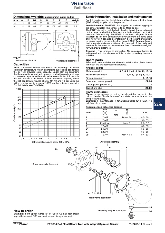
Note: Capacities shown are based on discharge at steam
saturation temperature. When discharging sub-cooled condensate
the air vent provides extra capacity. Under start-up conditions
the thermostatic air vent will be open, and will provide additional
condensate capacity to the main valve assembly. On 4.5 bar units
this will provide a minimum of 50% increased capacity above
the hot condensate figures shown. On 10 and 14 bar units this
will be a minimum increase of 100% on the published capacity.
For full details see TI-S02-28.
����
���
���
���
���
���
��
��
��
��
���
��� ��� ���
�
� � � �
�� ��
Available spares
Maintenance kit
Main valve assembly
Air vent assembly
Sensor and sensor gasket
Cover gasket (packet of 3)
Gasket and plug
How to order spares
3, 5, 6, 7 (2 off), 8, 10, 11,
3, 5, 6, 7 (2 off), 8,
3,
17, 18
10, 11
17, 18
24, 25
3
20, 29
Differential pressure bar (x 100 = kPa)
29
2 (not an available spare)
Air vent assembly
20
18
17
3
How to order
Example: 1 off Spirax Sarco 1⁄2" IFTGS14-4.5 ball float steam
trap with screwed BSP connections and integral air vent.
6 511107
8
Main valve assembly
Blanking plug 27 not shown
25
24
Withdrawal distance
Steam traps
Ball float
F
G
���
��
��
���������
C
o
n
d
e
n
s
a
t
e
k
g
/
h
IFTGS14 Ball Float Steam Trap with Integral Spiratec Sensor
TI-P615-11 ST Issue 3
Always order spares by using the description given in the
column headed 'Available spares' and state the size, type of trap
and pressure range.
Example: 1 - Maintenance kit for a Spirax Sarco 1⁄2" IFTGS14-10
ball float steam trap.
5.5.26
Recommended tightening torques
Item
2
5
7
9
24
27
29
or
mm
N m
47 - 50
50 - 55
2.5 - 3.0
50 - 55
50 - 56
50 - 56
57 - 63
17 A/F
17 A/F
Pozidrive
17 A/F
24 A/F
22 A/F
19 A/F
M10 x 30
M4 x 6
M14 x 1.5

