Steam traps
Fixed temperature discharge
Dimensions/weight (approximate) in mm and kg
Safety information, installation and maintenance
For full details see the Installation and Maintenance Instructions
(IM-P084-02) supplied with the product.
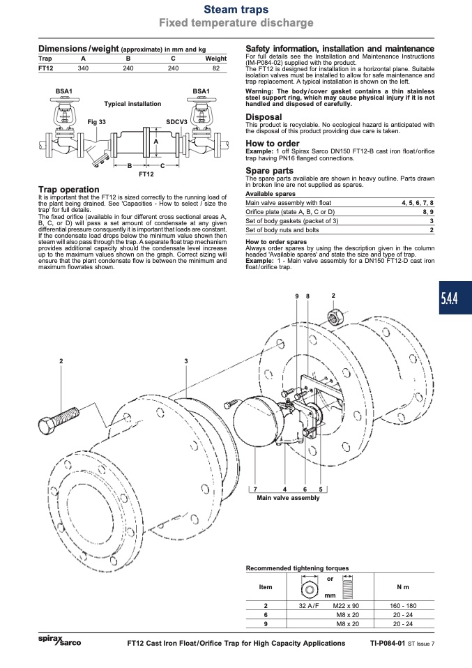
The FT12 is designed for installation in a horizontal plane. Suitable
isolation valves must be installed to allow for safe maintenance and
trap replacement. A typical installation is shown on the left.
Warning: The body / cover gasket contains a thin stainless
steel support ring, which may cause physical injury if it is not
handled and disposed of carefully.
Disposal
This product is recyclable. No ecological hazard is anticipated with
the disposal of this product providing due care is taken.
How to order
Example: 1 off Spirax Sarco DN150 FT12-B cast iron float/orifice
trap having PN16 flanged connections.
Spare parts
The spare parts available are shown in heavy outline. Parts drawn
in broken line are not supplied as spares.
Trap
FT12
A
340
B
C
240
240
Weight
82
BSA1
It is important that the FT12 is sized correctly to the running load of
the plant being drained. See 'Capacities - How to select / size the
trap' for full details.
The fixed orifice (available in four different cross sectional areas A,
B, C, or D) will pass a set amount of condensate at any given
differential pressure consquently it is important that loads are constant.
If the condensate load drops below the minimum value shown then
steam will also pass through the trap. A separate float trap mechanism
provides additional capacity should the condensate level increase
up to the maximum values shown on the graph. Correct sizing will
ensure that the plant condensate flow is between the minimum and
maximum flowrates shown.
2
3
BSA1
Typical installation
Fig 33
A
B
C
FT12
SDCV3
Trap operation
Available spares
Main valve assembly with float
Orifice plate (state A, B, C or D)
Set of body gaskets (packet of 3)
Set of body nuts and bolts
Always order spares by using the description given in the column
headed 'Available spares' and state the size and type of trap.
Example: 1 - Main valve assembly for a DN150 FT12-D cast iron
float / orifice trap.
9
8
2
4, 5, 6, 7, 8
8, 9
3
2
How to order spares
7
4
6
5
Main valve assembly
Recommended tightening torques
Item
Nm
or
mm
32 A/F
M22 x 90
2
6
9
160 - 180
20 - 24
20 - 24
M8 x 20
M8 x 20
FT12 Cast Iron Float/Orifice Trap for High Capacity Applications
TI-P084-01 ST Issue 7
5.4.4

