Steam traps
Fixed temperature discharge
5.4.3
ISO 9001
Steam
saturation
curve
Maximum load
Minimu m load
TI-P084-01
ST Issue 7
FT12
Cast Iron
Float/Orifice Trap for High Capacity Applications
Cert. No. LRQ 0963008
Description
The FT12 is a unique steam trap which combines a large fixed orifice
to handle very high condensate loads up to differential pressures of
4 bar. An integral float trap mechanism provides a variable capacity
in addition to the orifce. Minimum flowrates are required to avoid
blowthrough and these depend on the orifice selected A, B, C or D.
The FT12 is manufactured in cast iron with DN150 (6") flanged
connections. It is designed specifically for the sugar industry, which
has inherently low pressure, high load steam systems.
This product fully complies with the requirements of the European
Pressure Equipment Directive 97/23/EC.
This product is available with certification to EN 10204 2.2.
Note: Allcertification/inspection requirements must be stated at
the time of order placement.
Size and pipe connections
DN150, flanged PN16 and ANSI 125
(Flanges to BS 10 Table D can be supplied to special order).
Limiting conditions
Body design conditions
PMA - Maximum allowable pressure
TMA - Maximum allowable temperature
PMO - Maximum operating pressure
TMO - Maximum operating temperature
Designed for a maximum cold hydraulic test pressure of 24 bar g
Operating range
220
200
150
100
50
0
0
2
4*
6
8
10
12
14
16
Pressure bar g
1
2
7
3
1
Standards
Certification
PN16
16 bar g
220°C
4 bar g
220°C
8
9
6
5
4
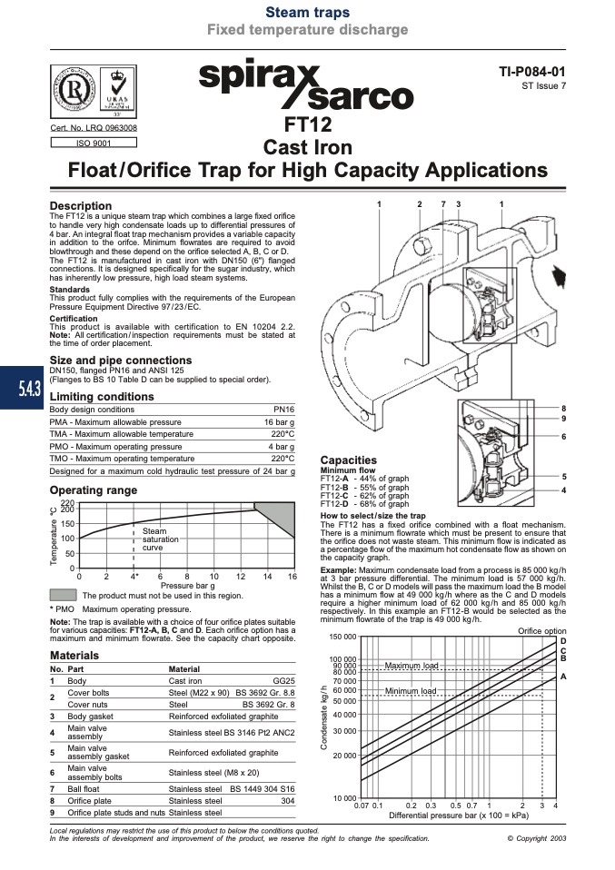
Capacities
Minimum flow
FT12-A - 44% of graph
FT12-B - 55% of graph
FT12-C - 62% of graph
FT12-D - 68% of graph
The FT12 has a fixed orifice combined with a float mechanism.
There is a minimum flowrate which must be present to ensure that
the orifice does not waste steam. This minimum flow is indicated as
a percentage flow of the maximum hot condensate flow as shown on
the capacity graph.
Example: Maximum condensate load from a process is 85 000 kg/h
at 3 bar pressure differential. The minimum load is 57 000 kg/h.
Whilst the B, C or D models will pass the maximum load the B model
has a minimum flow at 49 000 kg/h where as the C and D models
require a higher minimum load of 62 000 kg/h and 85 000 kg/h
respectively. In this example an FT12-B would be selected as the
minimum flowrate of the trap is 49 000 kg/h.
* PMO
The product must not be used in this region.
Maximum operating pressure.
Note: The trap is available with a choice of four orifice plates suitable
for various capacities: FT12-A, B, C and D. Each orifice option has a
maximum and minimum flowrate. See the capacity chart opposite.
150 000
100 000
90 000
80 000
70 000
60 000
50 000
40 000
30 000
20 000
10 000
0.07 0.1
Orifice option
D
C
B
A
How to select/size the trap
Materials
No. Part
1 Body
Material
GG25
BS 3692 Gr. 8.8
BS 3692 Gr. 8
Cover bolts
Cast iron
Steel (M22 x 90)
Steel
Reinforced exfoliated graphite
2
3 Body gasket
4
Main valve
assembly
5
Main valve
assembly gasket
6
Main valve
assembly bolts
7 Ball float
8 Orifice plate
9 Orifice plate studs and nuts
Cover nuts
Stainless steel BS 3146 Pt2 ANC2
Reinforced exfoliated graphite
Stainless steel (M8 x 20)
Stainless steel
Stainless steel
Stainless steel
BS 1449 304 S16
304
0.2
Differential pressure bar (x 100 = kPa)
3
0.3
0.5 0.7
1
2
4
Local regulations may restrict the use of this product to below the conditions quoted.
In the interests of development and improvement of the product, we reserve the right to change the specification.
© Copyright 2003
C
o
n
d
e
n
s
a
t
e
k
g
/
h
T
e
m
p
e
r
a
t
u
r
e
°
C

