Steam traps
Balanced pressure
5.2.17
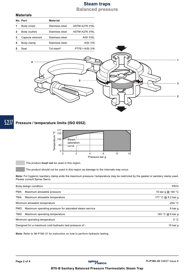
Steam
saturation
curve
Materials
No. Part
1 Body (inlet)
2 Body (outlet)
3 Capsule element
4 Body clamp
5 Seal
4
Material
Stainless steel
Stainless steel
Stainless steel
Stainless steel
Tuf-steel
®
ASTM A276 316L
ASTM A276 316L
AISI 316L
AISI 316
PTFE + AISI 316
5
1
3
2
Pressure / temperature limits (ISO 6552)
The product must not be used in this region.
Pressure bar g
The product should not be used in this region as damage to the internals may occur.
Note: For hygienic / sanitary clamp ends the maximum pressure / temperature may be restricted by the gasket or sanitary clamp used.
Please consult Spirax Sarco.
Body design condition
PMA Maximum allowable pressure
TMA Maximum allowable temperature
Minimum allowable temperature
PMO Maximum operating pressure for saturated steam service
TMO Maximum operating temperature
Minimum operating temperature
Designed for a maximum cold hydraulic test pressure of :
Note: Refer to IM-P180-31 for instruction on how to perform hydraulic testing.
PN10
10 bar g @ 140 °C
177 °C @ 9.2 bar g
-254 °C
6 bar g
165 °C @ 6 bar g
0 °C
15 bar g
Page 2 of 4
TI-P180-30 CMGT Issue 8
BT6-B Sanitary Balanced Pressure Thermostatic Steam Trap
T
e
m
p
e
r
a
t
u
r
e
°
C

