5.2.1
Steam
saturation
curve
Steam traps
BPT13
Brass
Balanced Pressure Thermostatic Steam Trap
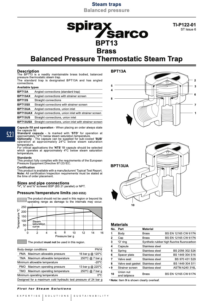
BPT13A
5
4
8
Balanced pressure
Local regulations may restrict the use of this product to below the conditions quoted.
In the interests of development and improvement of the product, we reserve the right to change the specification without notice.
© Copyright 2015
TI-P122-01
ST Issue 6
Description
The BPT13 is a readily maintainable brass bodied, balanced
pressure thermostatic steam trap.
The standard trap is designated BPT13A and has angled
connections.
2
3
6
7
1
Available types
BPT13A
Angled connections (standard trap)
BPT13AX Angled connections with strainer screen
BPT13S
Straight connections
BPT13SX Straight connections with strainer screen
BPT13UA Angled connections, union inlet
BPT13UAX Angled connections, union inlet with strainer screen
BPT13US Straight connections, union inlet
BPT13USX Straight connections, union inlet with strainer screen
Capsule fill and operation - When placing an order always state
the capsule fill:
Standard capsule - Is marked with 'STD' for operation at
approximately 12°C below steam saturation temperature.
Optionally - The capsule can be supplied for sub-cooled 'SUB'
operation at approximately 24°C below steam saturation
temperature.
For critical applications the 'NTS' fill capsule should be selected
which operates at approximately 4°C below steam saturation
temperature.
Standards
This product fully complies with the requirements of the European
Pressure Equipment Directive 97/23/EC.
This product is available with a manufacturers' Typical Test Report.
Note: All certification/inspection requirements must be stated at
the time of order placement.
Sizes and pipe connections
", 1⁄2" and 3⁄4" screwed BSP (BS 21 parallel) or NPT.
Pressure/temperature limits (ISO 6552)
The product should not be used in this region or beyond its
operating range as damage to the internals may occur.
������
������
������
������
����
��
BPT13UA
10
Certification
��
��
��
��
��
����
����
����
����
Pressure bar g
Materials
No. Part
Material
The product must not be used in this region.
Body design conditions
1
2
3
4
5
6
7
8
9
10
Body
Cap
'O' ring
Capsule
Spring
Spacer plate
Valve seat
Valve seat gasket
Strainer screen
Union nut
and tailpiece
Brass
Brass
Synthetic rubber high fluorine fluorocarbon
Stainless steel
Stainless steel
Stainless steel
Stainless steel
Stainless steel
Stainless steel
BS EN 12165 CW 617N
BS EN 12165 CW 617N
PN16
16 bar g @ 120°C
250°C @ 7 bar g
-20°C
13 bar g @ 220°C
250°C @ 7 bar g
0°C
Designed for a maximum cold hydraulic test pressure of 24 bar g
BS 2056 302 S26
BS 1449 304 S16
BS 970 431 S29
BS 1449 304 S11
ASTM A240 316L
PMA Maximum allowable pressure
TMA Maximum allowable temperature
Minimum allowable temperature
PMO Maximum operating pressure
*
TMO Maximum operating temperature
Minimum operating temperature
Brass
BS EN 12165 CW 617N
* Note: Item 9 is shown clearly overleaf.
T
e
m
p
e
r
a
t
u
r
e
°
C

