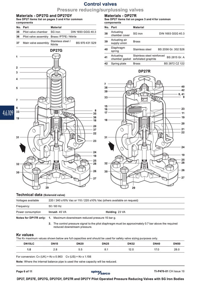
Materials - DP27G and DP27GY
See DP27 items list on pages 3 and 4 for common
components
Materials - DP27R
See DP27 items list on pages 3 and 4 for common
components
No. Part
35 Pilot valve chamber
36 Pilot valve assembly
37 Main valve assembly
1
2
3
4
5
7
6
4.6.109
33
19
31
32
30
Material
Stainless steel /
Nitrile
DP27G
No. Part
Material
SG iron
Brass
Stainless steel
29
Technical data (Solenoid valve)
29
Voltages available
Frequency
Power consumption
Notes for DP17R only:
Kv values
220 / 240 ±10% Vac or 110 / 220 ±10% Vac (others available on request)
50 / 60 Hz
Inrush 45 VA
Holding 23 VA
1. Maximum downstream reduced pressure 15 bar g.
Control valves
Pressure reducing/surplussing valves
SG iron
Brass / PTFE / Nitrile
Actuating
chamber cover
Actuating air
supply union
Diaphragm
spring
Actuating
chamber gasket
Spring plate
DIN 1693 GGG 40.3
BS 970 431 S29
38
39
40
41
42
7
38
39
33
15
16
17
DIN 1693 GGG 40.3
BS 2056 Gr. 302 S26
The Kv maximum values shown below are full capacities and should be used for safety valve sizing purposes only.
DN15LC
DN15
1.0
2.8
DN20
DN25
DN32
5.5
8.1
12.0
Cv (US) = Kv x 1.156
DN40
DN50
17.0
28.0
For conversion: Cv (UK) = Kv x 0.963
Note: Where the internal balance pipe is used the valve capacity will be reduced.
8
35
40
42
8, 41
9
23
11
19
20
21
22
24
19
25
28
26
27
36
18
18
20
37
22
23
24
19
25
28
32
26
30
27
TI-P470-01 CH Issue 10
DP27, DP27E, DP27G, DP27GY, DP27R and DP27Y Pilot Operated Pressure Reducing Valves with SG Iron Bodies
Page 6 of 11
31
2. The control pressure signal to the pilot diaphragm must be approximately 0.7 bar above the required
reduced downstream pressure.
Stainless steel reinforced
BS 2815 Gr. A
exfoliated graphite
Brass
BS 2872 CZ 122
DP27R

