Control valves
Pressure reducing/surplussing valves
Pressure/temperature limits
������
������
������������
������
��
������
�
�
�
�
�
�
�
�
�
�
���
�
���
�
���
�
����
Pressure bar g
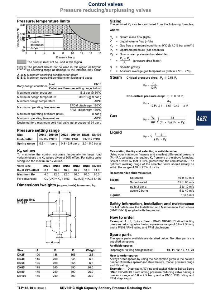
The product must not be used in this region.
The product should not be used in this region or beyond
its operating range as damage to the internals may occur.
A-B-C Maximum operating conditions for steam
D-E-C Maximum operating conditions for liquids and gases
Body design conditions
Inlet
PN16
Outlet see 'Pressure setting range' below
Sizing
The required Kv can be calculated from the following formulae,
where:
A
B
E
C
D
Steam
saturation
curve
s
g
P
1
P
2
c
S
T
= Steam mass flow (kg/h)
= Liquid volume flow (m
3
/h)
= Gas flow at standard conditions: 0°C @ 1.013 bar a (m3/h)
= Upstream pressure (bar absolute)
= Downstream pressure (bar absolute)
=
P
1
- P
2
(pressure drop factor)
P
1
= Specific gravity
= Absolute average gas temperature (Kelvin = °C + 273)
Maximum design pressure
Maximum design temperature
Minimum design temperature
15.2 bar @ 50°C
300°C @ 9 bar g
-10°C
EPDM diaphragm 130°C
Steam Critical pressure drop:
P
2
0.58 P
1
Non-critical pressure drop: P
2
0.58 P
1
Gas
Liquid
Calculating the Kv and selecting a suitable valve
Using your maximum flowrate and smallest differential pressure
(P
1
– P
2
), calculate the required Kv from one of the above formulae.
Select a valve Kv that is 30% greater than the calculated Kv. The
optimum working range of the selected valve should ideally be
within the range of 10 to 70% of its Kv.
Maximum operating temperature
diaphragm 180°C
8 bar g
-10°C
FPM
Designed for a maximum cold hydraulic test pressure of 24 bar g
Maximum operating pressure (inlet)
Minimum operating temperature
Pressure setting range
Size
Inlet / outlet
Spring range
Kv values
DN25 - DN100
PN16 / PN10
2.0 - 5.0 bar g
DN40 - DN100
DN25 - DN100
PN16 / PN2.5
PN16 / PN6
0.3 - 1.1 bar g
0.8 - 2.5 bar g
To maximise the control accuracy (especially for large load
variations) use the Kv values given at 20% offset. For safety valve
sizing use the maximum Kv values.
Valve size
Kv at 20% offset
Maximum Kv
For conversion:
Dimensions/weights (approximate) in mm and kg
DN25
DN40 DN50
DN65
DN80 DN100
3.1
4.0
Cv (UK) = Kv x 0.93
16.9 16.9
22.0 22.0
46.2
60.0
Cv (US) = Kv x 1.156
53.9 61.6
70.0 80.0
Recommended fluid velocities
B
A
Steam
Gas
Liquids
Saturated
Superheated
up to 2 bar g
above 2 bar g
10 to 40 m/s
15 to 60 m/s
2 to 10 m/s
5 to 40 m/s
1 to 5 m/s
Leakage line,
" BSP
Safety information, installation and maintenance
For full details see the Installation and Maintenance Instructions
(IM-P186-11) supplied with the product.
How to order
Example: 1 off, Spirax Sarco DN40 SRV66HC direct acting
pressure reducing valve having a pressure range of 0.8 – 2.5 bar g
and a PN16 / PN6 rating and FPM diaphragm.
Spare parts
The spare parts available are detailed below. No other parts are
supplied as spares.
Available spares
C
A
Size
A
DN25
100
DN40
115
DN50
125
DN65
175
DN80
175
DN100
175
B
C
Weight
Diaphragm, 'O' ring and gasket kit
10, 11, 12, 13, 17, 20
Always order spares by using the description given in the column
headed 'Available spares' and state the size, model, pressure range
and PN rating.
Example: 1 - Diaphragm, 'O' ring and gasket kit for a Spirax Sarco
DN40 SRV66HC direct acting pressure reducing valve having a
pressure range of 0.8 – 2.5 bar g and a PN16/PN6 rating and
FPM diaphragm.
138
305
2.5
How to order spares
200
345
200
355
6.5
240
690
26.0
6.5
240
690
240
690
26.0
26.0
TI-P186-10 CH Issue 3
SRV66HC High Capacity Sanitary Pressure Reducing Valve
4.6.92
T
e
m
p
e
r
a
t
u
r
e
°
C

