Control valves
Pressure reducing/surplussing valves
Sizing and selection for water applications
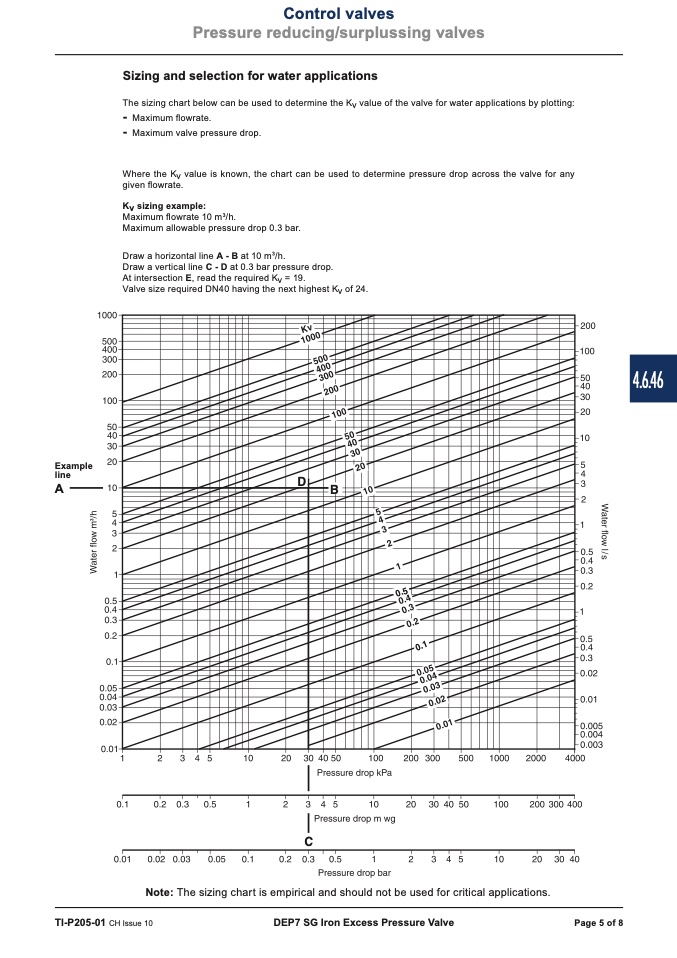
The sizing chart below can be used to determine the Kv value of the valve for water applications by plotting:
-
Maximum flowrate.
-
Maximum valve pressure drop.
Where the Kv value is known, the chart can be used to determine pressure drop across the valve for any
given flowrate.
Kv sizing example:
Maximum flowrate 10 m
3
/h.
Maximum allowable pressure drop 0.3 bar.
Draw a horizontal line A - B at 10 m
3
/h.
Draw a vertical line C - D at 0.3 bar pressure drop.
At intersection E, read the required Kv = 19.
Valve size required DN40 having the next highest Kv of 24.
Example
line
��
A
��
������
������
��
Note: The sizing chart is empirical and should not be used for critical applications.
TI-P205-01 CH Issue 10
DEP7 SG Iron Excess Pressure Valve
Page 5 of 8
4.6.46

