Control valves
Pressure reducing/surplussing valves
4.6.39
Sizing and selection
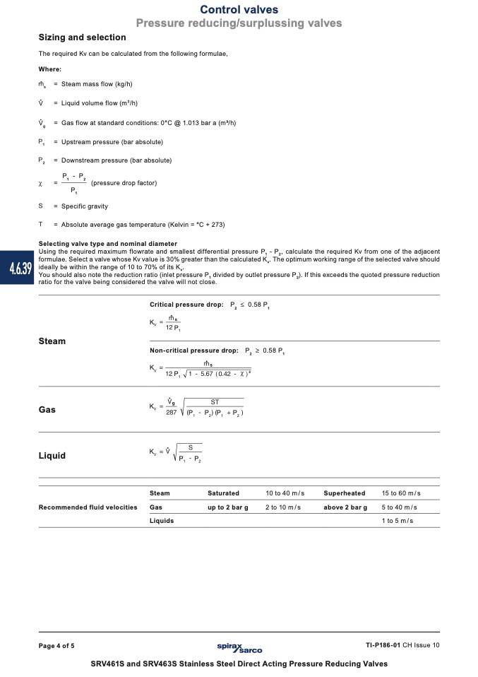
The required Kv can be calculated from the following formulae,
Where:
= Steam mass flow (kg/h)
= Liquid volume flow (m
3
/h)
= Gas flow at standard conditions: 0°C @ 1.013 bar a (m3/h)
= Upstream pressure (bar absolute)
= Downstream pressure (bar absolute)
=
P
1
- P
2
(pressure drop factor)
P
1
= Specific gravity
= Absolute average gas temperature (Kelvin = °C + 273)
Selecting valve type and nominal diameter
Using the required maximum flowrate and smallest differential pressure P
1
- P
2
, calculate the required Kv from one of the adjacent
formulae. Select a valve whose Kv value is 30% greater than the calculated K
v
. The optimum working range of the selected valve should
ideally be within the range of 10 to 70% of its K
v
.
You should also note the reduction ratio (inlet pressure P
1
divided by outlet pressure P
2
). If this exceeds the quoted pressure reduction
ratio for the valve being considered the valve will not close.
Critical pressure drop: P
2
£ 0.58 P
1
K
V
Non-critical pressure drop: P
2
P
1
Steam
Gas
Liquid
Recommended fluid velocities
0.58 P
1
K
V
1
P
K
V
2
P
1
P
2
P
1
P
2
K
V
Steam
Gas
Liquids
P
1
P
2
Saturated
up to 2 bar g
10 to 40 m / s
2 to 10 m/s
Superheated
above 2 bar g
15 to 60 m / s
5 to 40 m/s
1 to 5 m/s
Page 4 of 5
TI-P186-01 CH Issue 10
SRV461S and SRV463S Stainless Steel Direct Acting Pressure Reducing Valves

