Control valves
Pressure reducing/surplussing valves
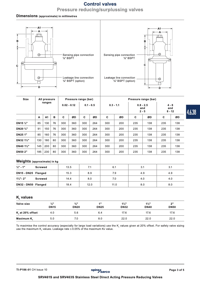
Dimensions (approximate) in millimetres
A1
A
B
B
A1
A
Sensing pipe connection
1⁄4" BSPT
Leakage line connection
1⁄4" BSPT (option)
Sensing pipe connection
1⁄4" BSPT
C
C
Leakage line connection
1⁄4" BSPT (option)
D
D
All pressure
ranges
Pressure range (bar)
0.02 - 0.12
0.1 - 0.5
A
A1
B C
ØD
C ØD
85
130
76 300
360
300 264
91
150
76 300
360
300 264
85
160
76 300
360
300 264
130
180
80 300
360
300 264
145
200
80 300
360
300 264
185
230
80 300
360
300 264
Size
Pressure range (bar)
0.8 - 2.5
and
2 - 5
0.3 - 1.1
4 - 8
and
8 - 12
C
ØD
C
ØD C
300
200
235
138 235
300
200
235
138 235
300
200
235
138 235
300
200
235
138 235
300
200
235
138 235
300
200
235
138 235
DN15 1⁄2"
DN20 3⁄4"
DN25 1"
DN32 11⁄4"
DN40 11⁄2"
DN50 2"
Weights (approximate) in kg
ØD
138
138
138
138
138
138
13.5
7.1 6.1 3.1
15.3
8.9 7.9 4.9
14.4
8.0 7.0 4.0
18.4
12.0 11.0 8.0
1⁄2" - 1"
DN15 - DN25
11⁄4"- 2"
DN32 - DN50
K
v
values
Valve size
Screwed
Flanged
Screwed
Flanged
3.1
4.9
4.0
8.0
K
v
at 20% offset
Maximum K
v
1⁄2"
DN15
4.0
5.0
3⁄4"
DN20
5.6
7.0
1"
DN25
6.4
8.0
11⁄4"
DN32
17.6
22.0
11⁄2"
DN40
17.6
22.0
2"
DN50
17.6
22.0
To maximise the control accuracy (especially for large load variations) use the K
v
values given at 20% offset. For safety valve sizing
use the maximum K
v
values. Leakage rate £ 0.05% of the maximum Kv value.
TI-P186-01 CH Issue 10
Page 3 of 5
SRV461S and SRV463S Stainless Steel Direct Acting Pressure Reducing Valves
4.6.38

