Control valves
Pressure reducing/surplussing valves
Dimensions (approximate) in millimetres
Flanged
Screwed
Actuator type
Size
EN 1092 ASME
BSP / NPT
PN25
150
1
2
3
4
5+6
A1
A1
A2
E
B
C
B
C
B
C
B
C
B
C
DN15
130
127
88
38
537
305
511
250
426
208
426
168
411
143
DN20
150
143
102
38
537
305
511
250
426
208
426
168
411
143
DN25
160
153
134
51
546
305
520
250
435
208
435
168
420
143
DN32
180
176
144
51
608
305
582
250
497
208
497
168
482
143
DN40
200
198
150
62
608
305
582
250
497
208
497
168
482
143
DN50
230
229
180
71
611
305
585
250
500
208
500
168
485
143
DN65
290
295
-
-
633
305
607
250
522
208
522
168
507
143
DN80
310
314
-
-
639
305
613
250
528
208
528
168
513
143
DN100
350
350
-
-
744
305
718
250
633
208
633
168
618
143
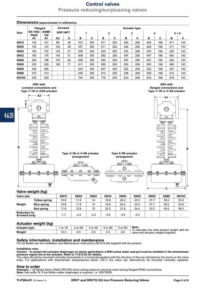
DRV with
screwed connections and
Type 1/1N or 2/2N actuator
A2
E
4.6.35
B
Valve weight (kg)
Valve size
Yellow spring
Weight
Blue spring
Red spring
Reduction for
Screwed body
Actuator weight (kg)
Actuator type
Weight
DRV with
flanged connections and
Type 1/1N or 2/2N actuator
Safety information, installation and maintenance
Type 3/3N or 4/4N actuator
arrangement
Type 5/5N actuator
arrangement
DN15
10.8
10.8
11.8
-1.7
1 or 1N
12.3
DN20
11.8
11.8
12.8
-2.2
2 or 2N
6.5
DN25
14
14
15
-2.2
3 or 3N
3.9
DN32
18.8
18.8
20.2
-3.6
4 or 4N
2.5
DN40
DN50
20.4
23.0
20.4
23.0
21.8
24.4
-3.9
-5.5
5 or 5N
2.6
C
DN65
DN80
DN100
For full details see the Installation and Maintenance Instructions (IM-S12-04) supplied with the product.
Installation note:
Caution - To protect the actuator diaphragm on steam applications a WS4 series water seal pot must be installed in the downstream
pressure signal line to the actuator. Refer to TI-S12-03 for details.
The valve should be mounted vertically downwards in a horizontal pipeline with the direction of flow as indicated by the arrow on the valve
body. For applications with downstream temperatures below 125°C the valve can alternatively be mounted vertically upwards.
How to order
Example: 1 off Spirax Sarco DN40 DRV7B3 direct acting pressure reducing valve having flanged PN40 connections.
Note: Add suffix 'N' if the Nitrile rubber diaphragm is required. i.e. DRV7B3N.
TI-P204-01 CH Issue 14
DRV7 and DRV7G SG Iron Pressure Reducing Valves
Page 6 of 6
Note:
A1
31.7
38.2
53.9
31.7
38.2
53.9
33.5
40.0
56.5
-
-
-
To calculate the total product weight add the
valve and actuator weights together.
B

