Control valves
Pressure reducing/surplussing valves
Capacities
Spare parts
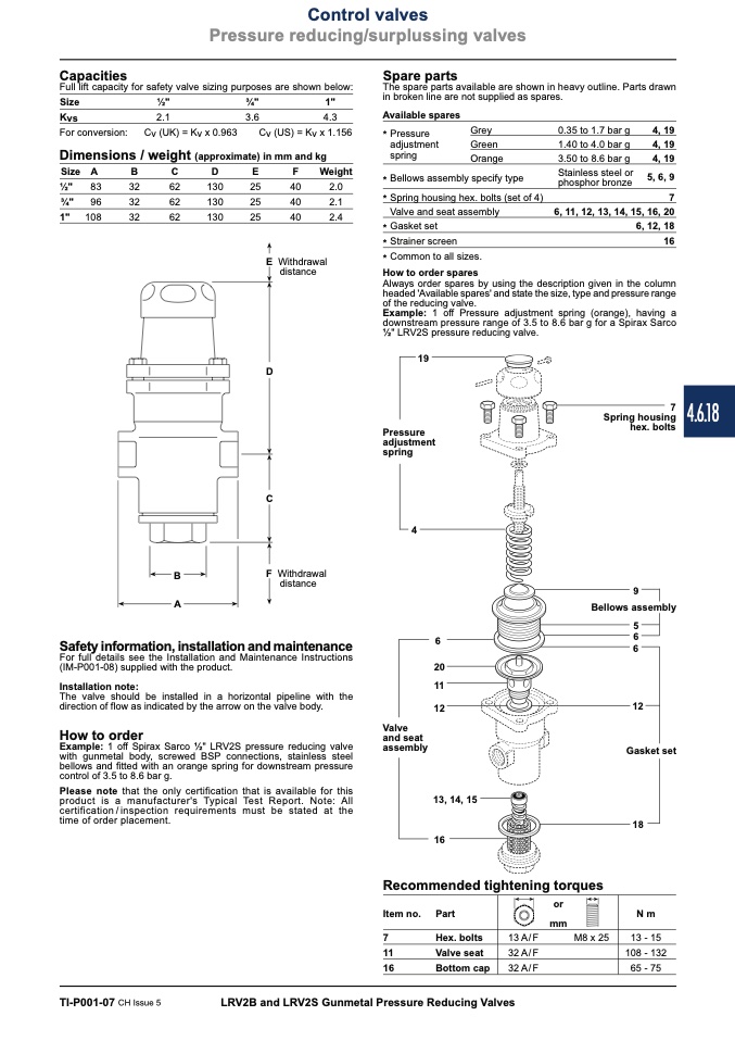
The spare parts available are shown in heavy outline. Parts drawn
in broken line are not supplied as spares.
Full lift capacity for safety valve sizing purposes are shown below:
Size
Kvs
For conversion:
1⁄2"
2.1
Cv (UK) = Kv x 0.963
3⁄4"
1"
3.6
4.3
Cv (US) = Kv x 1.156
Available spares
* Pressure
Grey
adjustment
Green
spring
Orange
* Bellows assembly specify type
* Spring housing hex. bolts (set of 4)
Valve and seat assembly
* Gasket set
* Strainer screen
* Common to all sizes.
How to order spares
0.35 to 1.7 bar g
1.40 to 4.0 bar g
3.50 to 8.6 bar g
Stainless steel or
phosphor bronze
4, 19
4, 19
4, 19
5, 6, 9
Dimensions / weight (approximate) in mm and kg
SizeA
B
C
D
E
F
Weight
1⁄2"
83
32
62
130
25
40
2.0
3⁄4" 96
32
62
130
25
40
2.1
7
6, 11, 12, 13, 14, 15, 16, 20
6, 12, 18
16
1" 108
32
62
130
25
40
Withdrawal
distance
2.4
Always order spares by using the description given in the column
headed 'Available spares' and state the size, type and pressure range
of the reducing valve.
Example: 1 off Pressure adjustment spring (orange), having a
downstream pressure range of 3.5 to 8.6 bar g for a Spirax Sarco
1⁄2" LRV2S pressure reducing valve.
19
Pressure
adjustment
spring
4
7
Spring housing
hex. bolts
F
Withdrawal
distance
9
Bellows assembly
5
B
A
Safety information, installation and maintenance
6
6
6
For full details see the Installation and Maintenance Instructions
(IM-P001-08) supplied with the product.
The valve should be installed in a horizontal pipeline with the
direction of flow as indicated by the arrow on the valve body.
How to order
Example: 1 off Spirax Sarco 1⁄2" LRV2S pressure reducing valve
with gunmetal body, screwed BSP connections, stainless steel
bellows and fitted with an orange spring for downstream pressure
control of 3.5 to 8.6 bar g.
Please note that the only certification that is available for this
product is a manufacturer's Typical Test Report. Note: All
certification/inspection requirements must be stated at the
time of order placement.
20
11
12
13, 14, 15
16
Installation note:
Valve
and seat
assembly
12
Gasket set
18
N m
13 - 15
108 - 132
65 - 75
Recommended tightening torques
Item no.
7
11
16
Part
Hex. bolts
Valve seat
Bottom cap
or
mm
13 A/F
M8 x 25
32 A/F
32 A/F
TI-P001-07 CH Issue 5
LRV2B and LRV2S Gunmetal Pressure Reducing Valves
E
D
C
4.6.18

