4.5.49
Control valves
Self-acting controls
Local regulations may restrict the use of this product to below the conditions quoted.
In the interests of development and improvement of the product, we reserve the right to change the specification without notice.
© Copyright 2013
TI-P073-03
CH Issue 7
Type 130 and HL10
'Safeguard High Limit Control'
Description
The Spirax Sarco safeguard high limit control system is supplied set
to cut-out at approximately 60°C and is designed to protect plant
from overheating. Note: the settings can easily be altered to initiate
cut-out at anywhere between 0°C and 100°C.
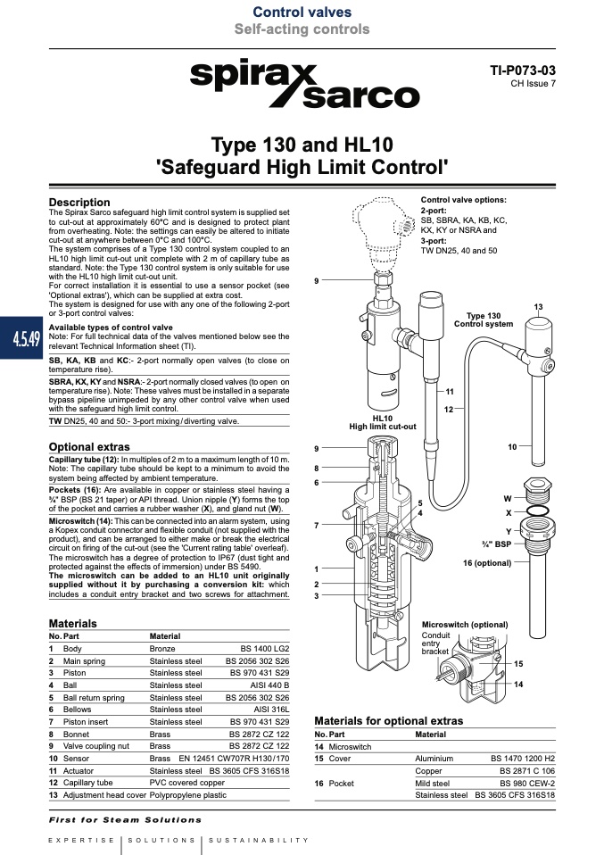
The system comprises of a Type 130 control system coupled to an
HL10 high limit cut-out unit complete with 2 m of capillary tube as
standard. Note: the Type 130 control system is only suitable for use
with the HL10 high limit cut-out unit.
For correct installation it is essential to use a sensor pocket (see
'Optional extras'), which can be supplied at extra cost.
The system is designed for use with any one of the following 2-port
or 3-port control valves:
Available types of control valve
Note: For full technical data of the valves mentioned below see the
relevant Technical Information sheet (TI).
SB, KA, KB and KC:- 2-port normally open valves (to close on
temperature rise).
SBRA, KX, KY and NSRA:- 2-port normally closed valves (to open on
temperature rise). Note: These valves must be installed in a separate
bypass pipeline unimpeded by any other control valve when used
with the safeguard high limit control.
Control valve options:
2-port:
SB, SBRA, KA, KB, KC,
KX, KY or NSRA and
3-port:
TW DN25, 40 and 50
9
Type 130
Control system
11
12
10
5
W
4
X
Y
3⁄4" BSP
16 (optional)
Microswitch (optional)
13
TW DN25, 40 and 50:- 3-port mixing / diverting valve.
Optional extras
9
Capillary tube (12): In multiples of 2 m to a maximum length of 10 m.
Note: The capillary tube should be kept to a minimum to avoid the
8
HL10
High limit cut-out
system being affected by ambient temperature.
6
Microswitch (14): This can be connected into an alarm system, using
7
a Kopex conduit connector and flexible conduit (not supplied with the
product), and can be arranged to either make or break the electrical
circuit on firing of the cut-out (see the 'Current rating table' overleaf).
The microswitch has a degree of protection to IP67 (dust tight and
protected against the effects of immersion) under BS 5490.
The microswitch can be added to an HL10 unit originally
supplied without it by purchasing a conversion kit: which
2
includes a conduit entry bracket and two screws for attachment.
Pockets (16): Are available in copper or stainless steel having a
3⁄4" BSP (BS 21 taper) or API thread. Union nipple (Y) forms the top
of the pocket and carries a rubber washer (X), and gland nut (W).
1
3
Materials
No. Part
1 Body
2 Main spring
3 Piston
4 Ball
5 Ball return spring
6 Bellows
7 Piston insert
8 Bonnet
9 Valve coupling nut
10 Sensor
11 Actuator
12 Capillary tube
13 Adjustment head cover
Material
Conduit
entry
bracket
Bronze
Stainless steel
Stainless steel
Stainless steel
Stainless steel
Stainless steel
Stainless steel
Brass
Brass
Brass
Stainless steel BS 3605 CFS 316S18
PVC covered copper
Polypropylene plastic
BS 1400 LG2
BS 2056 302 S26
BS 970 431 S29
AISI 440 B
BS 2056 302 S26
AISI 316L
BS 970 431 S29
BS 2872 CZ 122
BS 2872 CZ 122
EN 12451 CW707R H130/170
15
14
Materials for optional extras
No. Part
14 Microswitch
Material
Aluminium
Copper
Mild steel
Stainless steel
15
16
Cover
BS 1470 1200 H2
BS 2871 C 106
BS 980 CEW-2
BS 3605 CFS 316S18

