Flowmetering
Turbine flowmeters
Isolation valve (RIM10-600)
2" full-port bronze gate valve, 8.62 bar g (125 psi g) maximum. For RIM10-900 and 900H, see 'Accessories' below.
Pressure tap and bleed valve
Standard 1⁄4" NPT pipe nipple with 1⁄4" stainless steel bleed valve. Provides connections for mounting the optional pressure transmitter.
Temperature sensor
A 100 Ω, platinum RTD mounted inside the stem of the flowmeter probe, eliminating the need for a separate temperature tap.
Accessories
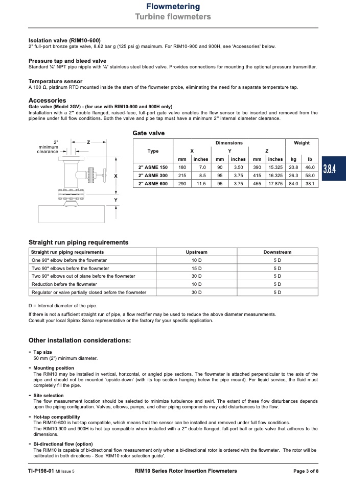
Gate valve (Model 2GV) - (for use with RIM10-900 and 900H only)
Installation with a 2" double flanged, raised-face, full-port gate valve enables the flow sensor to be inserted and removed from the
pipeline under full flow conditions. Both the valve and pipe tap must have a minimum 2" internal diameter clearance.
Gate valve
X
Y
Straight run piping requirements
D = Internal diameter of the pipe.
If there is not a sufficient straight run of pipe, a flow rectifier may be used to reduce the above diameter measurements.
Consult your local Spirax Sarco representative or the factory for your specific application.
Other installation considerations:
- Tap size
50 mm (2") minimum diameter.
- Mounting position
The RIM10 may be installed in vertical, horizontal, or angled pipe sections. The flowmeter is attached perpendicular to the axis of the
pipe and should not be mounted 'upside-down' (with its top section hanging below the pipe mount). For liquid service, the fluid must
completely fill the pipe.
- Site selection
The flow measurement location should be selected to minimize turbulence and swirl. The extent of these flow disturbances depends
upon the piping configuration. Valves, elbows, pumps, and other piping components may add disturbances to the flow.
- Hot-tap compatibility
The RIM10-600 is hot-tap compatible, which means that the sensor can be installed and removed under full flow conditions.
The RIM10-900 and 900H is hot tap compatible when installed with a 2" double flanged, full-port ball or gate valve that adheres to the
dimensions.
- Bi-directional flow (option)
The RIM10 is capable of bi-directional flow measurement only when a bi-directional rotor is ordered with the flowmeter. The rotor will be
calibrated in both directions - See 'RIM10 rotor selection guide'.
Type
Dimensions
X
Y
Z
mm inches mm inches mm inches
Weight
kg
lb
2" ASME 150
180
7.0
90
3.50
390
15.325
20.8 46.0
2" ASME 300 215
8.5 95
3.75 415
16.325 26.3 58.0
2" ASME 600
290
11.5
95
3.75
455
17.875
84.0 38.1
2"
Z
minimum
clearance
Straight run piping requirements
Upstream Downstream
One 90° elbow before the flowmeter
10 D 5D
Two 90° elbows before the flowmeter
15 D 5D
Two 90° elbows out of plane before the flowmeter 30 D 5D
Reduction before the flowmeter
10 D 5D
Regulator or valve partially closed before the flowmeter 30 D 5D
TI-P198-01 MI Issue 5
RIM10 Series Rotor Insertion Flowmeters
Page 3 of 8
3.8.4

