Flowmetering
Orifice plate flowmeters
Dimensions / weights (approximate) in mm and kg
EN 1092 EN 1092
EN 1092
BS 10:
ASME
ASME
ASME
JIS
KS
Maximum
PN16
PN25
PN40
Table H
150
300
600
20
20
weight
Size
A
A
A
A
A
A
A
A
A
kg
DN25
73
73
73
71.4
DN40
94
94
94
88.9
DN50
109
109
109
111.1
DN65
129
129
129
130.1
DN80
144
144
144
149.2
DN100
164
170
170
174.6
DN125
194
196
196
215.9
DN150
220
226
226
241.3
DN200
275
286
293
304.9
DN250
331
343
355
358.8
DN300
386
403
420
415.9
DN350
446
460
477
469.9
DN400
498
517
549
527.0
DN450
559
567
574
581.0
DN500
620
627
631
644.5
DN600
737
734
750
749.3
66.7
73.0
85.7
95.3
104.7
111.1
123.8
130.2
136.5
149.3
174.6
181.0
196.9
216.0
222.3
250.9
279.4
308.0
339.7
361.9
409.6
422.2
450.8
485.7
574.3
539.7
549.2
596.8
606.4
654.0
717.5
774.7
73.0
74
95.3
89
111.1
104
130.2
124
149.3
140
193.7
165
241.3
203
266.7
238
320.6
383
400.0
356
457.1
406
492.1
450
565.1
570
612.7
575
682.6
630
790.6
734
74
2.36
89
3.72
104
4.91
124
6.21
140
7.91
165
13.75
203
20.98
238
23.51
383
31.25
356
47.95
400
58.74
450
60.20
570
85.99
575
94.38
630
117.69
734
146.37
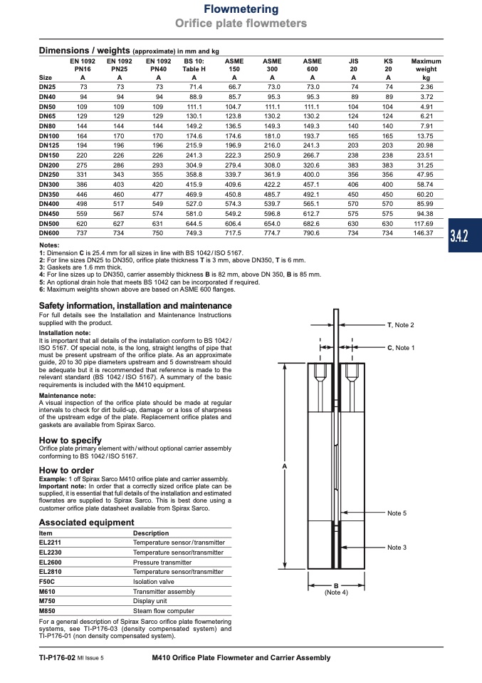
T, Note 2
C, Note 1
Notes:
1: Dimension C is 25.4 mm for all sizes in line with BS 1042 / ISO 5167.
2: For line sizes DN25 to DN350, orifice plate thickness T is 3 mm, above DN350, T is 6 mm.
3: Gaskets are 1.6 mm thick.
4: For line sizes up to DN350, carrier assembly thickness B is 82 mm, above DN 350, B is 85 mm.
5: An optional drain hole that meets BS 1042 can be incorporated if required.
6: Maximum weights shown above are based on ASME 600 flanges.
Safety information, installation and maintenance
For full details see the Installation and Maintenance Instructions
supplied with the product.
Installation note:
It is important that all details of the installation conform to BS 1042 /
ISO 5167. Of special note, is the long, straight lengths of pipe that
must be present upstream of the orifice plate. As an approximate
guide, 20 to 30 pipe diameters upstream and 5 downstream should
be adequate but it is recommended that reference is made to the
relevant standard (BS 1042 / ISO 5167). A summary of the basic
requirements is included with the M410 equipment.
Maintenance note:
A visual inspection of the orifice plate should be made at regular
intervals to check for dirt build-up, damage or a loss of sharpness
of the upstream edge of the plate. Replacement orifice plates and
gaskets are available from Spirax Sarco.
How to specify
Orifice plate primary element with / without optional carrier assembly
conforming to BS 1042 / ISO 5167.
How to order
Example: 1 off Spirax Sarco M410 orifice plate and carrier assembly.
Important note: In order that a correctly sized orifice plate can be
supplied, it is essential that full details of the installation and estimated
flowrates are supplied to Spirax Sarco. This is best done using a
customer orifice plate datasheet available from Spirax Sarco.
Note 5
Note 3
Associated equipment
Item
Description
EL2211
Temperature sensor/transmitter
EL2230
Temperature sensor/transmitter
EL2600
Pressure transmitter
EL2810
Temperature sensor/transmitter
F50C
Isolation valve
M610
Transmitter assembly
(Note 4)
M750
Display unit
M850
Steam flow computer
For a general description of Spirax Sarco orifice plate flowmetering
systems, see TI-P176-03 (density compensated system) and
TI-P176-01 (non density compensated system).
B
TI-P176-02 MI Issue 5
M410 Orifice Plate Flowmeter and Carrier Assembly
A
3.4.2

