Flowmetering
Local regulations may restrict the use of this product to below the conditions quoted.
Target flowmeters
In the interests of development and improvement of the product, we reserve the right to change the specification without notice. © Copyright 2016
TI-P193-01
MI Issue 4
TFA
Flowmeter for
Saturated Steam Service
Description
The Spirax Sarco TFA flowmeter is designed for use on saturated steam only and
operates on the target principle, by measuring the force produced on a target by
the fluid flow. This force is then converted into density compensated mass flowrate
or power and is transmitted via a single loop powered 4-20 mA and pulsed output.
TFA flowmeters also incorporate a totalised flow function and EIA 232C (RS232)
or EIA 485C (RS485) Modbus communications.
Sizes and pipe connections
The TFA flowmeter is of wafer design, available in the listed specified sizes suitable
for fitting between the following flanges:
DN25, DN32, DN40 and DN50
Flanged EN 1092-1 PN16, PN25 and PN40,
Japanese Industrial Standard JIS 20 and
Korean Standard KS 20
1", 11⁄4", 11⁄2" and 2"
Flanged ASME B 16.5 Class 150 and Class 300
Note:
The Spirax Sarco TFA flowmeter should be installed in pipework manufactured
to BS 1600, ASME B 36.10 Schedule 40 or EN 10216-2 / EN 10216-5 equivalent.
For systems with different standards / schedules, please contact Spirax Sarco.
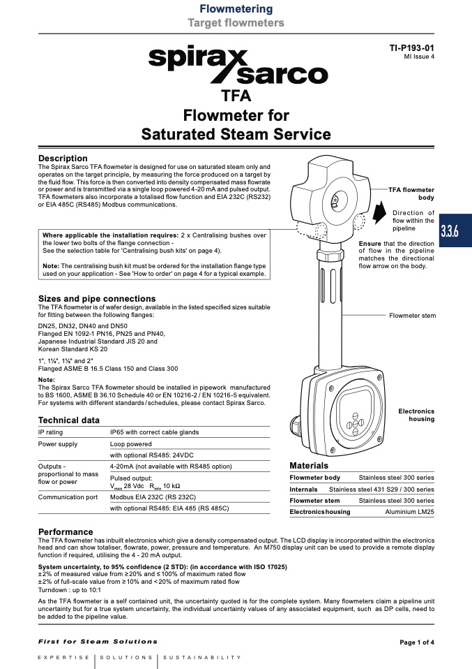
TFA flowmeter
body
Direction of
flow within the
pipeline
Ensure that the direction
of flow in the pipeline
matches the directional
flow arrow on the body.
Flowmeter stem
Electronics
housing
Stainless steel 300 series
Where applicable the installation requires: 2 x Centralising bushes over
the lower two bolts of the flange connection -
See the selection table for 'Centralising bush kits' on page 4).
Note: The centralising bush kit must be ordered for the installation flange type
used on your application - See 'How to order' on page 4 for a typical example.
Technical data
IP rating
Power supply
Outputs -
proportional to mass
flow or power
Communication port
Performance
IP65 with correct cable glands
Loop powered
with optional RS485: 24VDC
4-20mA (not available with RS485 option)
Pulsed output:
V
max
28 Vdc R
min
10 kW
Modbus EIA 232C (RS 232C)
with optional RS485: EIA 485 (RS 485C)
Materials
Flowmeter body
Internals
Stainless steel 431 S29 / 300 series
Flowmeter stem
Stainless steel 300 series
Electronicshousing
Aluminium LM25
The TFA flowmeter has inbuilt electronics which give a density compensated output. The LCD display is incorporated within the electronics
head and can show totaliser, flowrate, power, pressure and temperature. An M750 display unit can be used to provide a remote display
function if required, utilising the 4 - 20 mA output.
System uncertainty, to 95% confidence (2 STD): (in accordance with ISO 17025)
± 2% of measured value from ≥ 20% and ≤ 100% of maximum rated flow
± 2% of full-scale value from ≥ 10% and < 20% of maximum rated flow
Turndown : up to 10:1
As the TFA flowmeter is a self contained unit, the uncertainty quoted is for the complete system. Many flowmeters claim a pipeline unit
uncertainty but for a true system uncertainty, the individual uncertainty values of any associated equipment, such as DP cells, need to
be added to the pipeline value.
Page 1 of 4
3.3.6

