Flowmetering
Gilflo and ILVA flowmeters
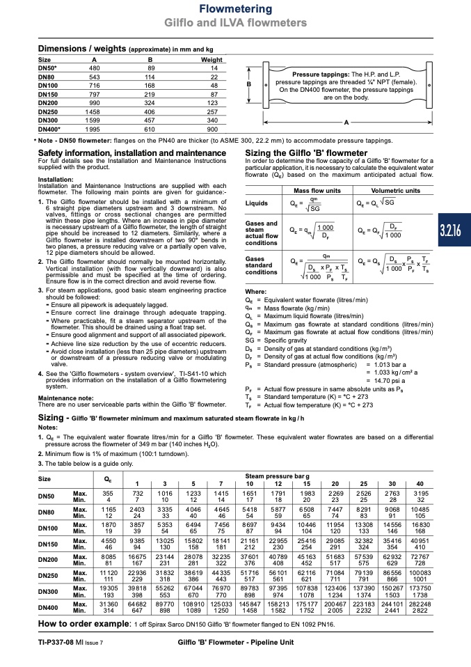
Dimensions / weights (approximate) in mm and kg
Size
A
DN50*
480
DN80
543
DN100
716
DN150
797
DN200
990
DN250
1 458
DN300
1 599
DN400*
1 995
B
Weight
89
14
114
22
168
48
219
87
324
123
406
257
457
340
610
900
Pressure tappings: The H.P. and L.P.
pressure tappings are threaded 1⁄4" NPT (female).
On the DN400 flowmeter, the pressure tappings
are on the body.
* Note - DN50 flowmeter: flanges on the PN40 are thicker (to ASME 300, 22.2 mm) to accommodate pressure tappings.
Safety information, installation and maintenance
For full details see the Installation and Maintenance Instructions
supplied with the product.
Installation and Maintenance Instructions are supplied with each
flowmeter. The following main points are given for guidance:-
1. The Gilflo flowmeter should be installed with a minimum of
6 straight pipe diameters upstream and 3 downstream. No
valves, fittings or cross sectional changes are permitted
within these pipe lengths. Where an increase in pipe diameter
is necessary upstream of a Gilflo flowmeter, the length of straight
pipe should be increased to 12 diameters. Similarily, where a
Gilflo flowmeter is installed downstream of two 90° bends in
two planes, a pressure reducing valve or a partially open valve,
12 pipe diameters should be allowed.
2. The Gilflo flowmeter should normally be mounted horizontally.
Vertical installation (with flow vertically downward) is also
permissible and must be specified at the time of ordering.
Ensure flow is in the correct direction and avoid reverse flow.
Sizing the Gilflo 'B' flowmeter
In order to determine the flow capacity of a Gilflo 'B' flowmeter for a
particular application, it is necessary to calculate the equivalent water
flowrate (Q
E
) based on the maximum anticipated actual flow.
Installation:
Mass flow units
Q
E
=
q
m
SG
Q
E
= q
m
1 000
D
F
Q
E
=
q
m
D
S
xP
F
xT
S
1 000 P
S
T
F
355
4
1 165
12
1 870
19
4 550
46
8 085
81
11 120
111
19 305
193
31 360
314
732
7
2 403
24
3 857
39
9 385
94
16 675
167
22 936
229
39 818
398
64 682
647
1 016
10
3 335
33
5 353
54
13 025
130
23 144
231
31 832
318
55 262
553
89 770
898
1 233
12
4 046
40
6 494
65
15 802
158
28 078
281
38 619
386
67 044
670
108 910
1 089
1 415
14
4 645
46
7 456
75
18 141
181
32 235
322
44 335
443
76 970
770
125 033
1 250
B
Liquids
Gases and
steam
actual flow
conditions
Gases
standard
conditions
Volumetric units
Q
E
= Q
L
SG
1 651
17
5 418
54
8 697
87
21 161
212
37 601
376
51 716
517
89 783
898
145 847
1 458
D
1 000
Mass flowrate (kg / min)
Maximum liquid flowrate (litres/min)
Maximum gas flowrate at standard conditions (litres / min)
Maximum gas flowrate at actual flow conditions (litres / min)
Specific gravity
Density of gas at standard conditions (kg / m
3
)
Density of gas at actual flow conditions (kg / m
3
)
Standard pressure (atmospheric) = 1.013 bar a
= 1.033 kg / cm
2
a
= 14.70 psi a
Actual flow pressure in same absolute units as P
S
Standard temperature (K) = °C + 273
Actual flow temperature (K) = °C + 273
1 791
18
5 877
59
9 434
94
22 955
230
40 789
408
56 101
561
97 395
974
158 213
1 582
1 983
20
6 508
65
10 446
104
25 416
254
45 163
452
62116
621
107 838
1 078
175 177
1 752
2 269
23
7 447
74
11954
120
29 085
291
51 683
517
71 084
711
123 406
1 234
200 467
2 005
A
Q
E
Q
E
= Q
F
Q
E
= Q
S
F
2 526
25
8 291
83
13 308
133
32 382
324
57 539
575
79 139
791
137 390
1 374
223 183
2 232
D
P T
S
x
S
1 000 P
F
x
F
T
S
3. For steam applications, good basic steam engineering practice
should be followed:
Where:
Q
E
= Equivalent water flowrate (litres/min)
-
Ensure all pipework is adequately lagged.
-
Ensure correct line drainage through adequate trapping.
-
Where practicable, fit a steam separator upstream of the
q
m
=
Q
L
=
Q
S
=
Q
F
=
SG =
D
S
=
D
F
=
P
S
=
P
F
=
T
S
=
T
F
=
flowmeter. This should be drained using a float trap set.
-
Ensure good alignment and support of all associated pipework.
-
Achieve line size reduction by the use of eccentric reducers.
-
Avoid close installation (less than 25 pipe diameters) upstream
or downstream of a pressure reducing valve or modulating
valve.
4. See the 'Gilflo flowmeters - system overview', TI-S41-10 which
provides information on the installation of a Gilflo flowmetering
system.
Maintenance note:
There are no user serviceable parts within the Gilflo 'B' flowmeter.
Sizing - Gilflo 'B' flowmeter minimum and maximum saturated steam flowrate in kg / h
Notes:
1. Q
E
= The equivalent water flowrate litres/min for a Gilflo 'B' flowmeter. These equivalent water flowrates are based on a differential
pressure across the flowmeter of 349 m bar (140 inches H
2
O).
2. Minimum flow is 1% of maximum (100:1 turndown).
3. The table below is a guide only.
Size
Steam pressure bar g
1
3
5
7
10
12
15
20
25
30
40
Max.
Min.
Max.
Min.
Max.
Min.
Max.
Min.
Max.
Min.
Max.
Min.
Max.
Min.
Max.
Min.
TI-P337-08 MI Issue 7
Gilflo 'B' Flowmeter - Pipeline Unit
3 195
32
10 485
105
16 830
168
40 951
410
72 767
728
100 083
1001
173 750
1 738
282 248
2 822
DN50
DN80
DN100
DN150
DN200
DN250
DN300
DN400
How to order example:
1 off Spirax Sarco DN150 Gilflo 'B' flowmeter flanged to EN 1092 PN16.
2 763
28
9 068
91
14 556
146
35 416
354
62 932
629
86 556
866
150 267
1 503
244 101
2 441
3.2.16

