Flowmetering
Gilflo and ILVA flowmeters
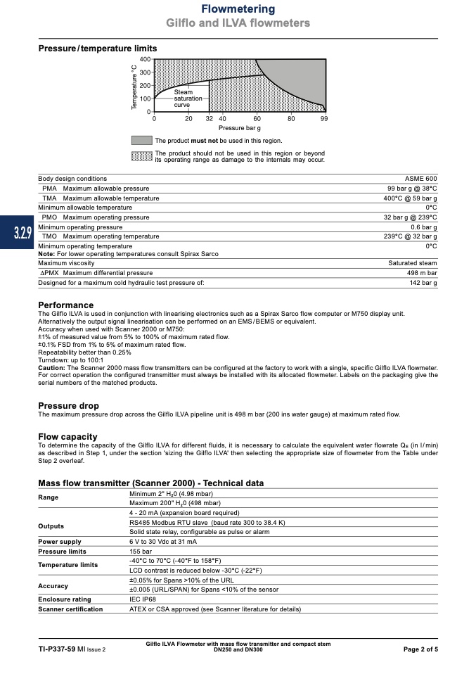
Steam
saturation
curve
3.2.9
Pressure/temperature limits
Pressure bar g
The product must not be used in this region.
The product should not be used in this region or beyond
its operating range as damage to the internals may occur.
Body design conditions
PMA Maximum allowable pressure
TMA Maximum allowable temperature
Minimum allowable temperature
PMO Maximum operating pressure
Minimum operating pressure
TMO Maximum operating temperature
Minimum operating temperature
Note: For lower operating temperatures consult Spirax Sarco
Maximum viscosity
DPMX Maximum differential pressure
Designed for a maximum cold hydraulic test pressure of:
Performance
ASME 600
99 bar g @ 38°C
400°C @ 59 bar g
0°C
32 bar g @ 239°C
0.6 bar g
239°C @ 32 bar g
0°C
Saturated steam
498 m bar
142 bar g
The Gilflo ILVA is used in conjunction with linearising electronics such as a Spirax Sarco flow computer or M750 display unit.
Alternatively the output signal linearisation can be performed on an EMS/BEMS or equivalent.
Accuracy when used with Scanner 2000 or M750:
±1% of measured value from 5% to 100% of maximum rated flow.
±0.1% FSD from 1% to 5% of maximum rated flow.
Repeatability better than 0.25%
Turndown: up to 100:1
Caution: The Scanner 2000 mass flow transmitters can be configured at the factory to work with a single, specific Gilflo ILVA flowmeter.
For correct operation the configured transmitter must always be installed with its allocated flowmeter. Labels on the packaging give the
serial numbers of the matched products.
Pressure drop
The maximum pressure drop across the Gilflo ILVA pipeline unit is 498 m bar (200 ins water gauge) at maximum rated flow.
Flow capacity
To determine the capacity of the Gilflo ILVA for different fluids, it is necessary to calculate the equivalent water flowrate Q
E
(in l/min)
as described in Step 1, under the section 'sizing the Gilflo ILVA' then selecting the appropriate size of flowmeter from the Table under
Step 2 overleaf.
Mass flow transmitter (Scanner 2000) - Technical data
Range
Outputs
Power supply
Pressure limits
Temperature limits
Accuracy
Enclosure rating
Scanner certification
TI-P337-59 MI Issue 2
Minimum 2" H
2
0 (4.98 mbar)
Maximum 200" H
2
0 (498 mbar)
4 - 20 mA (expansion board required)
RS485 Modbus RTU slave (baud rate 300 to 38.4 K)
Solid state relay, configurable as pulse or alarm
6 V to 30 Vdc at 31 mA
155 bar
-40°C to 70°C (-40°F to 158°F)
LCD contrast is reduced below -30°C (-22°F)
±0.05% for Spans >10% of the URL
±0.005 (URL/SPAN) for Spans <10% of the sensor
IEC IP68
ATEX or CSA approved (see Scanner literature for details)
Gilflo ILVA Flowmeter with mass flow transmitter and compact stem
DN250 and DN300
Page 2 of 5
T
e
m
p
e
r
a
t
u
r
e
°
C

