Flowmetering
Gilflo and ILVA flowmeters
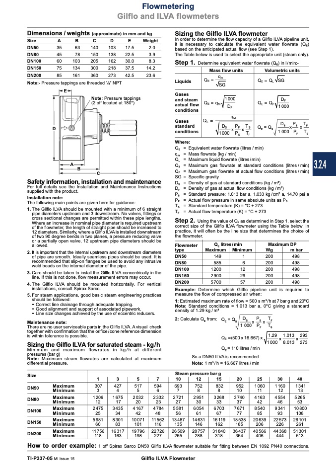
Dimensions / weights (approximate) in mm and kg
Size
A
B
C
D
E
Weight
E
Note: Pressure tappings
(2 off located at 180°)
A
B
C
Sizing the Gilflo ILVA flowmeter
In order to determine the flow capacity of a Gilflo ILVA pipeline unit,
it is necessary to calculate the equivalent water flowrate (Q
E
)
based on the anticipated actual flow (see Step 1).
The Table below is used to select the appropriate unit (steam only).
Step 1.
Determine equivalent water flowrate (Q
E
) in l/min:-
Volumetric units
DN50
35
DN80
45
DN100
60
DN150
75
DN200
85
Note:- Pressure tappings are threaded 1⁄4" NPT
63
140
103
17.5
2.0
78
150
103
205
134
300
161
360
138
22.5
162
30.0
8.3
218
37.5
14.2
273
42.5
23.6
3.9
Mass flow units
Q
E
=
q
m
SG
Q=q
1000
E
M
D
F
q
M
Q
E
=
D
S
x
P
F
x
T
S
1 000 P
S
T
F
Liquids
Gases
and steam
actual flow
conditions
Gases
standard
conditions
Where:
Q
E
= Q
L
Q
E
= Q
SG
D
F
1000
Q
E
litres/min
Maximum Minimum
F
D
Q
E
= Q
S
Ö
S
x
S
F
S
P
P
Q
S
= Maximum gas flowrate at standard conditions (litres / min)
Q
F
= Maximum gas flowrate at actual flow conditions (litres / min)
SG = Specific gravity
D
S
= Density of gas at standard conditions (kg / m3)
D
1 000
T
x
F
T
Q
E
= Equivalent water flowrate (litres / min)
q
m
= Mass flowrate (kg / min)
Q
L
= Maximum liquid flowrate (litres/min)
Safety information, installation and maintenance
For full details see the Installation and Maintenance Instructions
supplied with the product.
D = Density of gas at actual flow conditions (kg / m3)
Installation note:
P
S
= Actual flow pressure in same absolute units as P
The following main points are given here for guidance:
T
F
= Standard temperature (K) = °C + 273
S
1. The Gilflo ILVA should be mounted with a minimum of 6 straight
pipe diameters upstream and 3 downstream. No valves, fittings or
cross sectional changes are permitted within these pipe lengths.
Where an increase in nominal pipe diameter is required upstream
of the flowmeter, the length of straight pipe should be increased to
12 diameters. Similarly, where a Gilflo ILVA is installed downstream
of two 90 degree bends in two planes, a pressure reducing valve
or a partially open valve, 12 upstream pipe diameters should be
allowed.
Flowmeter
P
F
= Standard pressure: 1.013 bar a, 1.033 kg /cm
2
a, 14.70 psi a
T
S
= Actual flow temperature (K) = °C + 273
F
Step 2.
Using the value of Q
E
as determined in Step 1, select the
correct size of the Gilflo ILVA flowmeter using the Table below. In
practice, it will often be the line size that determines the choice of
the flowmeter.
Maximum DP
2. It is important that the internal upstream and downstream diameters
of pipe are smooth. Ideally seamless pipes should be used. It is
DN50
type
Wg
m bar
498
498
498
498
498
recommended that slip-on flanges be used to avoid any intrusive
weld beads on the internal diameter of the pipe.
3. Care should be taken to install the Gilflo ILVA concentrically in the
line. If this is not done, flow measurement errors may occur.
4. The Gilflo ILVA should be mounted horizontally. For vertical
installations, consult Spirax Sarco.
DN80
DN100
DN150
DN200
149
585
1 200
2 900
5 700
1
6
12
29
57
200
200
200
200
200
5. For steam applications, good basic steam engineering practices
should be followed:
-
Correct line drainage through adequate trapping.
-
Good alignment and support of associated pipework.
Example: Determine which Gilflo pipeline unit is required to
measure the flow of compressed air when:
1: Estimated maximum rate of flow = 500 s m3/h at 7 bar g and 20°C
Note: Standard conditions = 1.013 bar a, 0°C giving a standard
density of 1.29 kg / m3
2: Calculate Q from: Q = Q D
P
TD
P
P
E
E
S
S
S
F
S
F
F
-
Line size changes achieved by the use of eccentric reducers.
Maintenance note:
Q
E
=xQ
S
x
x
x
1 000 P
T
There are no user serviceable parts in the Gilflo ILVA. A visual check
together with confirmation that the orifice / cone reference dimension
is within tolerance is possible.
Ö
F
Q
E
=(500 x 16.667) x
Q = 110 litres / min
So a DN50 ILVA is recommended.
Note: 1 m3 / h = 16.667 litres / min
1000
x
8.013
x
273
1 0
S
0 0 P
S
T
S
1.29 1.013 293
Steam pressure bar g
1
3
5
7
10
12
15
20
25
30
40
1 341
13
5 265
53
10 800
108
26 101
261
51 301
513
Sizing the Gilflo ILVA for saturated steam - kg/h
Minimum and maximum flowrates in kg / h at different
pressures (bar g)
Note: Maximum steam flowrates are calculated at maximum
differential pressure.
E
Size
DN50
DN80
DN100
DN150
DN200
Maximum
Minimum
Maximum
Minimum
Maximum
Minimum
Maximum
Minimum
Maximum
Minimum
307
3
427
4
517
5
594
6
693
7
752
8
832
8
952
10
1 060
11
1 160
12
1 206
12
1 675
17
2 032
20
2 332
23
2 721
27
2 951
30
3 268
33
3 740
37
4 163
42
4 554
46
2 475
25
3 435
34
4 167
42
4 784
48
5 581
56
6 054
61
6 703
67
7 671
77
8 540
85
9 341
93
5 981
60
8 301
83
10 071
101
11562
116
13 487
135
14 631
146
16119
162
18 538
185
20 639
206
22 573
226
11756
118
16 317
163
19 796
198
22 726
227
26 509
265
28 757
288
31 840
318
36 437
364
40 566
406
44 368
444
How to order example:
1 off Spirax Sarco DN50 Gilflo
TI-P337-05 MI Issue 15
Gilflo ILVA Flowmeter
ILVA flowmeter suitable for fitting between EN 1092 PN40 connections.
3.2.4

