3.2.3
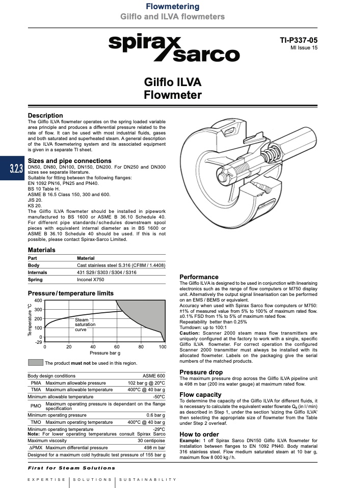
Steam
saturatio
curve
n
Flowmetering
Gilflo and ILVA flowmeters
Local regulations may restrict the use of this product to below the conditions quoted.
In the interests of development and improvement of the product, we reserve the right to change the specification without notice.
© Copyright 2013
TI-P337-05
MI Issue 15
Gilflo ILVA
Flowmeter
Description
The Gilflo ILVA flowmeter operates on the spring loaded variable
area principle and produces a differential pressure related to the
rate of flow. It can be used with most industrial fluids, gases
and both saturated and superheated steam. A general description
of the ILVA flowmetering system and its associated equipment
is given in a separate TI sheet.
Sizes and pipe connections
DN50, DN80, DN100, DN150, DN200. For DN250 and DN300
sizes see separate literature.
Suitable for fitting between the following flanges:
EN 1092 PN16, PN25 and PN40.
BS 10 Table H.
ASME B 16.5 Class 150, 300 and 600.
JIS 20.
KS 20.
The Gilflo ILVA flowmeter should be installed in pipework
manufactured to BS 1600 or ASME B 36.10 Schedule 40.
For different pipe standards/schedules downstream spool
pieces with equivalent internal diameter as in BS 1600 or
ASME B 36.10 Schedule 40 should be used. If this is not
possible, please contact Spirax-Sarco Limited.
Materials
Part
Material
Body
Cast stainless steel S.316 (CF8M / 1.4408)
Internals
431 S29 / S303 / S304 / S316
Spring
Inconel X750
Pressure/temperature limits
������
������
������
������
��
������
��
����
����
����
����
������
Performance
Pressure bar g
The product must not be used in this region.
The Gilflo ILVA is designed to be used in conjunction with linearising
electronics such as the range of flow computers or M750 display
unit. Alternatively the output signal linearisation can be performed
on an EMS / BEMS or equivalent.
Accuracy when used with Spirax Sarco flow computers or M750:
±1% of measured value from 5% to 100% of maximum rated flow.
±0.1% FSD from 1% to 5% of maximum rated flow.
Repeatability better than 0.25%
Turndown: up to 100:1
Caution: Scanner 2000 steam mass flow transmitters are
uniquely configured at the factory to work with a single, specific
Gilflo ILVA flowmeter. For correct operation the configured
Scanner 2000 transmitter must always be installed with its
allocated flowmeter. Labels on the packaging give the serial
numbers of the matched products.
Pressure drop
The maximum pressure drop across the Gilflo ILVA pipeline unit
is 498 m bar (200 ins water gauge) at maximum rated flow.
Flow capacity
To determine the capacity of the Gilflo ILVA for different fluids, it
is necessary to calculate the equivalent water flowrate Q (in l / min)
as described in Step 1, under the section 'sizing the Gilflo ILVA'
then selecting the appropriate size of flowmeter from the Table
under Step 2 overleaf.
How to order
Example: 1 off Spirax Sarco DN150 Gilflo ILVA flowmeter for
installation between flanges to EN 1092 PN40. Body material
316 stainless steel. Flow medium saturated steam at 10 bar g,
maximum flow 8 000 kg / h.
Body design conditions
PMA Maximum allowable pressure
TMA Maximum allowable temperature
Minimum allowable temperature
ASME 600
102 bar g @ 20°C
400°C @ 40 bar g
-50°C
PMO
Maximum operating pressure is dependant on the flange
specification
Minimum operating pressure
TMO Maximum operating temperature
Minimum operating temperature
E
0.6 bar g
400°C @ 40 bar g
-29°C
Note: For lower operating temperatures consult Spirax Sarco
Maximum viscosity
30 centipoise
DPMX Maximum differential pressure
498 m bar
Designed for a maximum cold hydraulic test pressure of 155 bar g
T
e
m
p
e
r
a
t
u
r
e
°
C

