Boiler house
Bottom blowdown systems
BBV43
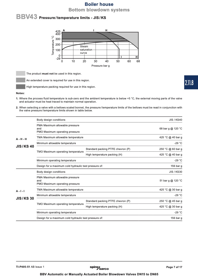
Pressure / temperature limits - JIS / KS
������A
I
H
������
������
������
������
��
������
��
����
����
����
����
����
����
����
Pressure bar g
������
������
������
������
Steam
The product must not be used in this region.
������
������
������
������
saturation
curve
An extended cover is requir
������
������
������
������
��
����
����
����
��
and actuator must be heat traced to maintain normal operation.
2. When selecting a valve with a bellows scaled bonnet, the pressure / temperature limits of the bellows must be read in conjunction with
the valve pressure / temperature limits shown in table below.
��
e d for use in this region.
����
High temperature packing required for use in this region.
����
Notes:
1. Where the process fluid temperature is sub-zero and the ambient temperature is below +5 °C, the external moving parts of the valve
�� ��
�� �� ��
���� ���� ���� ���� ���� ���� ���� ���� ���� ���� ���� ���� ���� ���� ���� ���� ���� ���� ���� ���� ���� ���� ���� ���� ���� ���� ���� ���� ���� ����
I
H
A-H-H
JIS/KS 40
Body design conditions
PMA Maximum allowable pressure
and
PMO Maximum operating pressure
TMA Maximum allowable temperature
Minimum allowable temperature
TMO Maximum operating temperature
Minimum operating temperature
Standard packing PTFE chevron (P)
High temperature packing (H)
JIS / KS40
68 bar g @ 120 °C
425 °C @ 40 bar g
-29 °C
250 °C @ 60 bar g
425 °C @ 40 bar g
-29 °C
156 bar g
JIS / KS30
51 bar g @ 120 °C
425 °C @ 30 bar g
-29 °C
250 °C @ 45 bar g
425 °C @ 30 bar g
-29 °C
156 bar g
Design for a maximum cold hydraulic test pressure of:
A-I-I
JIS/KS 30
Body design conditions
PMA Maximum allowable pressure
and
PMO Maximum operating pressure
TMA Maximum allowable temperature
Minimum allowable temperature
TMO Maximum operating temperature
Minimum operating temperature
Standard packing PTFE chevron (P)
High temperature packing (H)
Design for a maximum cold hydraulic test pressure of:
TI-P405-51 AB Issue 1
BBV Automatic or Manually Actuated Boiler Blowdown Valves DN15 to DN65
Page 7 of 17
2.11.8
T
e
m
p
e
r
a
t
u
r
e
°
C

