General information
Useful calculation data
���������
���������
���������
���������
���������
���������
11.5.5
ISO 9001
Cert. No. LRQ 0963008
= Mass flow in kg / h
= Upstream pressure in bar a
= Downstream pressure in bar a
= Valve flow coefficient.
P
1
- P
2
TI-GCM-08
CM Issue 1
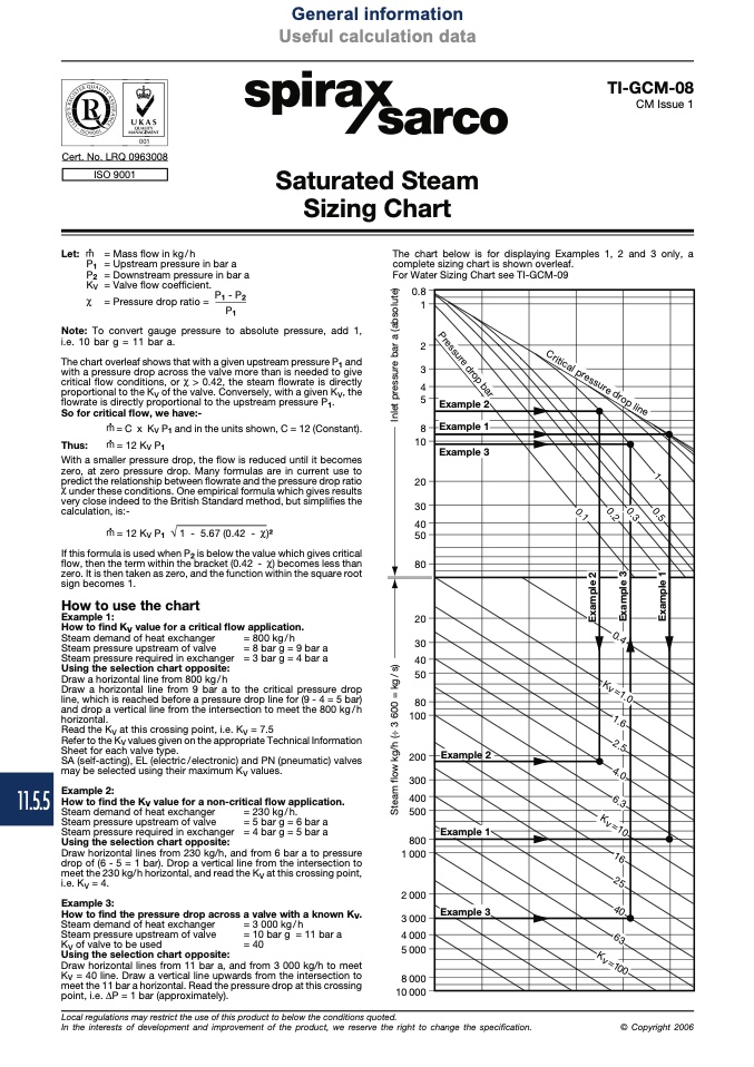
The chart below is for displaying Examples 1, 2 and 3 only, a
complete sizing chart is shown overleaf.
For Water Sizing Chart see TI-GCM-09
Saturated Steam
Sizing Chart
Let:
P
1
P
2
Kv
���
�
�
�
�
�
�
��
��
��
��
��
��
��
��
��
��
��
���
���
���
���
���
���
� ���
� ���
� ���
� ���
� ���
� ���
�� ���
i.e. 10 bar g = 11 bar a.
The chart overleaf shows that with a given upstream pressure P
1
and
with a pressure drop across the valve more than is needed to give
critical flow conditions, or > 0.42, the steam flowrate is directly
proportional to the Kv of the valve. Conversely, with a given Kv, the
flowrate is directly proportional to the upstream pressure P
1
.
So for critical flow, we have:-
= C x Kv P
1
and in the units shown, C = 12 (Constant).
Thus:
= 12 Kv P
1
With a smaller pressure drop, the flow is reduced until it becomes
zero, at zero pressure drop. Many formulas are in current use to
predict the relationship between flowrate and the pressure drop ratio
under these conditions. One empirical formula which gives results
very close indeed to the British Standard method, but simplifies the
calculation, is:-
= Pressure drop ratio =
P
1
Note: To convert gauge pressure to absolute pressure, add 1,
= 12 K P
v1
√ 1 - 5.67 (0.42 - )2
If this formula is used when P
2
is below the value which gives critical
flow, then the term within the bracket (0.42 - ) becomes less than
zero. It is then taken as zero, and the function within the square root
sign becomes 1.
How to use the chart
Example 1:
How to find Kv value for a critical flow application.
Steam demand of heat exchanger
Steam pressure upstream of valve
Steam pressure required in exchanger
Using the selection chart opposite:
Draw a horizontal line from 800 kg/h
Draw a horizontal line from 9 bar a to the critical pressure drop
line, which is reached before a pressure drop line for (9 - 4 = 5 bar)
and drop a vertical line from the intersection to meet the 800 kg / h
horizontal.
Read the Kv at this crossing point, i.e. Kv = 7.5
Refer to the Kv values given on the appropriate Technical Information
Sheet for each valve type.
SA (self-acting), EL (electric/electronic) and PN (pneumatic) valves
may be selected using their maximum Kv values.
Example 2:
How to find the Kv value for a non-critical flow application.
= 800 kg/h
= 8 bar g = 9 bar a
= 3 bar g = 4 bar a
Steam demand of heat exchanger
Steam pressure upstream of valve
Steam pressure required in exchanger
Using the selection chart opposite:
Draw horizontal lines from 230 kg/h, and from 6 bar a to pressure
drop of (6 - 5 = 1 bar). Drop a vertical line from the intersection to
meet the 230 kg/h horizontal, and read the Kv at this crossing point,
i.e. Kv = 4.
Example 3:
How to find the pressure drop across a valve with a known Kv.
= 230 kg/h.
= 5 bar g = 6 bar a
= 4 bar g = 5 bar a
Steam demand of heat exchanger
Steam pressure upstream of valve
Kv of valve to be used
Using the selection chart opposite:
Draw horizontal lines from 11 bar a, and from 3 000 kg/h to meet
Kv = 40 line. Draw a vertical line upwards from the intersection to
meet the 11 bar a horizontal. Read the pressure drop at this crossing
point, i.e. ∆P = 1 bar (approximately).
= 3 000 kg/h
= 10 bar g = 11 bar a
= 40
Local regulations may restrict the use of this product to below the conditions quoted.
In the interests of development and improvement of the product, we reserve the right to change the specification.
© Copyright 2006
���������������������������
���
���
�
�
�
�
�
�
�
�
�
�
�
�
�
�
�
�
�
�
�
�
�
�
�
�
�
�
�
�
�
�
�
�
�
�
�
�
�
�
�
�
�
�
�
�
�
�
�
�
�
�
�
�
�
�
�
�
�
�
�
�
�
�
�
�
�
�
�
�
�
�
�
�
�
�
�
�
�
�
�
�
�
�
�
�
�
�
�
�
�
�
���
�� ����
�� ���
������
���
���
���
��
��
��
��

