Compressed air products
Isolation valves, drain traps and ancillaries
Safety information, installation and maintenance
For full details see the Installation and Maintenance Instructions
(IM-P504-24) supplied with the product.
Installation note:
The Dri-Line should be fitted with the inlet port at the top, so that
the float mechanism can rise and fall vertically.
Spare parts
The spare parts available are detailed below. No other parts are
supplied as spares.
Available spares
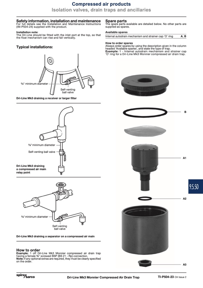
Internal autodrain mechanism and strainer cap 'O' ring
How to order spares
A, B
Typical installations:
" minimum diameter
Always order spares by using the description given in the column
headed 'Available spares', and state the type of trap.
Example: 1 - Internal autodrain mechanism and strainer cap
'O' ring for a Dri-Line Mk3 Monnier compressed air drain trap.
Self-venting
ball valve
Dri-Line Mk3 draining a receiver or larger filter
B
" minimum diameter
Self-venting ball valve
Dri-Line Mk3 draining
a compressed air main
relay point
" minimum diameter
A1
A2
Self-venting
ball valve
Dri-Line Mk3 draining a separator on a compressed air main
How to order
Example: 1 off Dri-Line Mk3 Monnier compressed air drain trap
having a female 1⁄2" screwed BSP (BS 21 - Rp) connection.
Note: If any optional extras are required, they must be clearly specified
on the order.
Dri-Line Mk3 Monnier Compressed Air Drain Trap
A3
TI-P504-23 CH Issue 2
9.5.50

