Pipeline ancillaries
Air vents and air eliminators
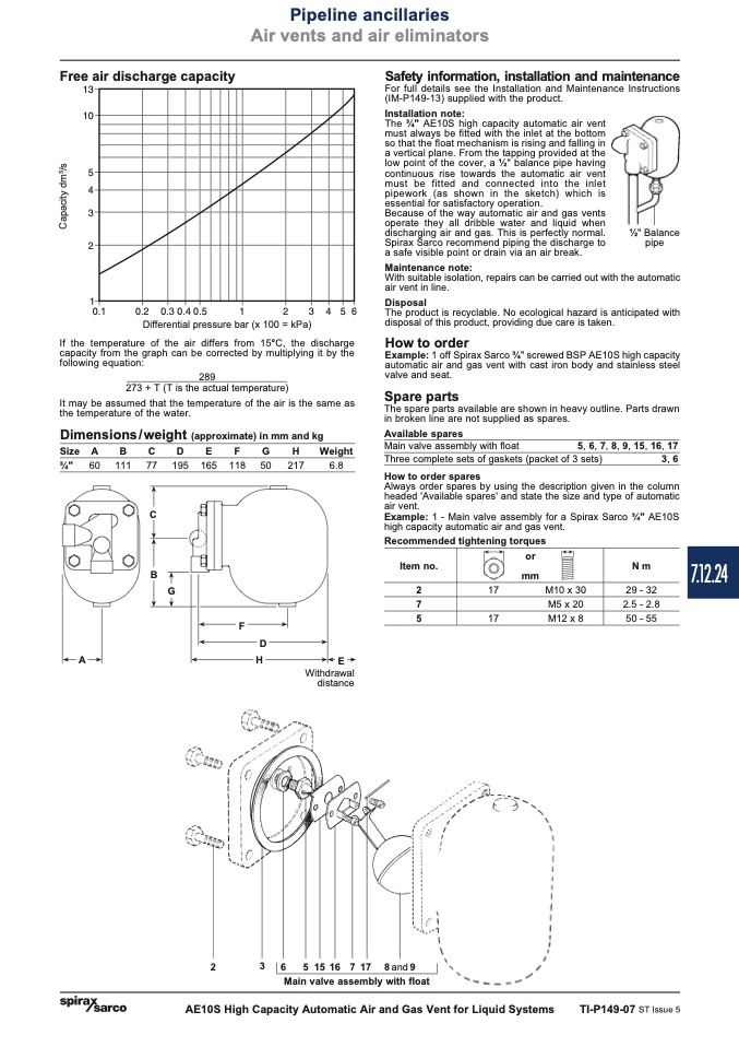
Free air discharge capacity
����
����
��
��
��
��
��
������
�����
�
������������������
��
�
�
�
�
������
Differential pressure bar (x 100 = kPa)
If the temperature of the air differs from 15°C, the discharge
capacity from the graph can be corrected by multiplying it by the
289
273 + T (T is the actual temperature)
It may be assumed that the temperature of the air is the same as
the temperature of the water.
Dimensions/weight (approximate) in mm and kg
Size A
B
C
D
E
F
G
H
Weight
Safety information, installation and maintenance
For full details see the Installation and Maintenance Instructions
(IM-P149-13) supplied with the product.
following equation:
Installation note:
The 3⁄4" AE10S high capacity automatic air vent
must always be fitted with the inlet at the bottom
so that the float mechanism is rising and falling in
a vertical plane. From the tapping provided at the
low point of the cover, a 1⁄2" balance pipe having
continuous rise towards the automatic air vent
must be fitted and connected into the inlet
pipework (as shown in the sketch) which is
essential for satisfactory operation.
Because of the way automatic air and gas vents
operate they all dribble water and liquid when
discharging air and gas. This is perfectly normal.
Spirax Sarco recommend piping the discharge to
a safe visible point or drain via an air break.
With suitable isolation, repairs can be carried out with the automatic
air vent in line.
The product is recyclable. No ecological hazard is anticipated with
disposal of this product, providing due care is taken.
How to order
Example: 1 off Spirax Sarco 3⁄4" screwed BSP AE10S high capacity
automatic air and gas vent with cast iron body and stainless steel
valve and seat.
Spare parts
The spare parts available are shown in heavy outline. Parts drawn
in broken line are not supplied as spares.
Available spares
Main valve assembly with float
Three complete sets of gaskets (packet of 3 sets)
3, 6
Always order spares by using the description given in the column
headed 'Available spares' and state the size and type of automatic
air vent.
Example: 1 - Main valve assembly for a Spirax Sarco 3⁄4" AE10S
high capacity automatic air and gas vent.
Maintenance note:
Disposal
1⁄2" Balance
pipe
5, 6, 7, 8, 9, 15, 16, 17
3⁄4" 60 111 77
C
B
195 165 118
G
50
217
6.8
How to order spares
Recommended tightening torques
Item no.
2
7
5
or
mm
N m
29 - 32
2.5 - 2.8
50 - 55
17
M10 x 30
M5 x 20
17
M12 x 8
F
D
A
H
E
Withdrawal
distance
2
3 6 51516 717
Main valve assembly with float
8and9
AE10S High Capacity Automatic Air and Gas Vent for Liquid Systems
TI-P149-07 ST Issue 5
7.12.24
C
a
p
a
c
i
t
y
d
m
3
/
s

