Boiler house
Sample coolers
Performance
Tables below show typical sample outlet temperatures above cooling water inlet temperatures for several pressures and cooling water flowrates.
Example
A sample flowrate of 30 I/h is required from a boiler operating at 10 bar g. For a cooling water flowrate of 0.3 I/s from Table 1 the sample outlet
temperature would be 4°C above the cooling water inlet temperature. If the cooling water is at 15°C, the sample temperature would
be 19°C.
Table 2 is used in the same way for steam.
Samples may not be taken where marked '-' as the flow is limited by the sample inlet valve capacity.
Table 1 Water
(e.g. WFI - water for injection)
Sample
flowrate
l/h
Cooling water flow
0.6 l/sec
Cooling water flowrate
0.1 l/sec
Cooling water flowrate
0.3 l/sec
Boiler pressure bar g
1
3
7
10
20
1
3
7
10
20
1
3
7
10
20
1°C
1°C
3°C
6°C
6°C
0°C
0°C
1°C
1°C
4°C
2°C
2°C
6°C
8°C
8°C
1°C
1°C
2°C
2°C
6°C
5°C
5°C
8°C 11°C 11°C
3°C
3°C
4°C
4°C
8°C
7°C
7°C
11°C 13°C 13°C
5°C
5°C
6°C
6°C 10°C
10°C 10°C 13°C 15°C 15°C
6°C
6°C
8°C
8°C 12°C
14°C 14°C 16°C 18°C 18°C
9°C
9°C 10°C 10°C 14°C
16°C 18°C 20°C 22°C 22°C
11°C 12°C 13°C 14°C 18°C
18°C 20°C 24°C 26°C 27°C
15°C 16°C 16°C 18°C 22°C
22°C 23°C 29°C 30°C 31°C
17°C 18°C 20°C 23°C 26°C
10
0°C
20
0°C
30
0°C
40
1°C
50
3°C
60
4°C
80
6°C
100
10°C
120
11°C
Table 2 Saturated steam
Sample
flowrate
kg/h
5
10
15
20
30
40
50
60
70
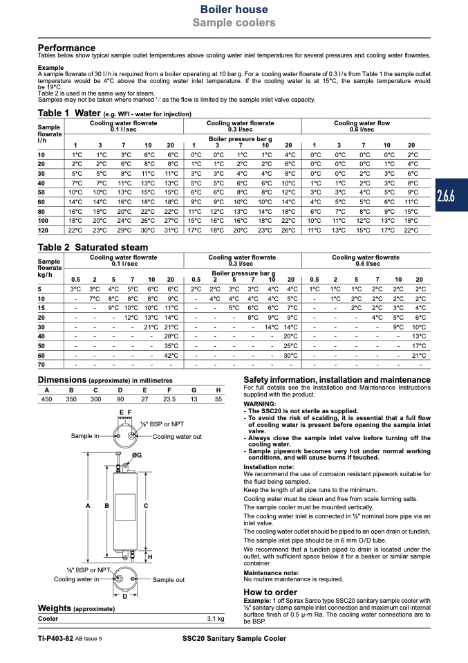
Dimensions (approximate) in millimetres
A
B
C
D
E
F
G
H
450
350
300
90
27
23.5
13
55
0°C
0°C
0°C
0°C
0°C
2°C
1°C
2°C
3°C
4°C
5°C
5°C
7°C
8°C
11°C 12°C
13°C 15°C
0°C
2°C
1°C
4°C
3°C
6°C
3°C
8°C
5°C
9°C
6°C 11°C
9°C 15°C
13°C 18°C
17°C 22°C
Cooling water flowrate
0.1 l/sec
Cooling water flowrate
0.3 l/sec
Cooling water flowrate
0.6 l/sec
Boiler pressure bar g
0.5
2
5
7
10
20
0.5
2
5
7
10
20
0.5
2
5
7
10
20
3°C 3°C 4°C 5°C 6°C 6°C
2°C 2°C 3°C 3°C 4°C 4°C
-
7°C 8°C 8°C 8°C 9°C
-
4°C 4°C 4°C 4°C 5°C
-
-
9°C 10°C 10°C 11°C
-
-
5°C 6°C 6°C 7°C
-
-
- 12°C 13°C 14°C
-
-
-
8°C 9°C 9°C
-
-
-
-
21°C21°C
-
-
-
-
14°C14°C
-
-
-
-
-
28°C
-
-
-
-
- 20°C
-
-
-
-
-
35°C
-
-
-
-
- 25°C
-
-
-
-
-
42°C
-
-
-
-
- 30°C
-
-
-
-
-
-
-
-
-
-
-
-
1°C 1°C 1°C 2°C
-
1°C 2°C 2°C
Safety information, installation and maintenance
For full details see the Installation and Maintenance Instructions
supplied with the product.
2°C 2°C
-
4°C
-
-
-
-
-
13°C
-
-
-
17°C
-
-
-
21°C
-
-
-
-
-
-
-
-
-
-
-
-
-
-
-
-
-
-
2°C
2°C
2°C
2°C
3°C
4°C
5°C
6°C
9°C 10°C
Sample in
valve.
- Always close the sample inlet valve before turning off the
EF
ØG
WARNING:
- The SSC20 is not sterile as supplied.
- To avoid the risk of scalding, it is essential that a full flow
1⁄2" BSP or NPT
Cooling water out
of cooling water is present before opening the sample inlet
cooling water.
- Sample pipework becomes very hot under normal working
conditions, and will cause burns if touched.
A
B
C
Installation note:
We recommend the use of corrosion resistant pipework suitable for
the fluid being sampled.
Keep the length of all pipe runs to the minimum.
Cooling water must be clean and free from scale forming salts.
The sample cooler must be mounted vertically.
The cooling water inlet is connected in 1⁄2" nominal bore pipe via an
inlet valve.
The cooling water outlet should be piped to an open drain or tundish.
The sample inlet pipe should be in 6 mm O/D tube.
We recommend that a tundish piped to drain is located under the
outlet, with sufficient space below it for a beaker or similar sample
container.
H
1⁄2" BSP or NPT
Cooling water in
Weights (approximate)
Cooler
Maintenance note:
D
How to order
Example: 1 off Spirax Sarco type SSC20 sanitary sample cooler with
1⁄2" sanitary clamp sample inlet connection and maximum coil internal
surface finish of 0.5 μ-m Ra. The cooling water connections are to
be BSP.
Sample out
No routine maintenance is required.
3.1 kg
TI-P403-82 AB Issue 5
SSC20 Sanitary Sample Cooler
2.6.6

