Pipeline ancillaries
Strainers and filters
B
C
Steam
saturation
curve
C
B
ED
A
7.7.43
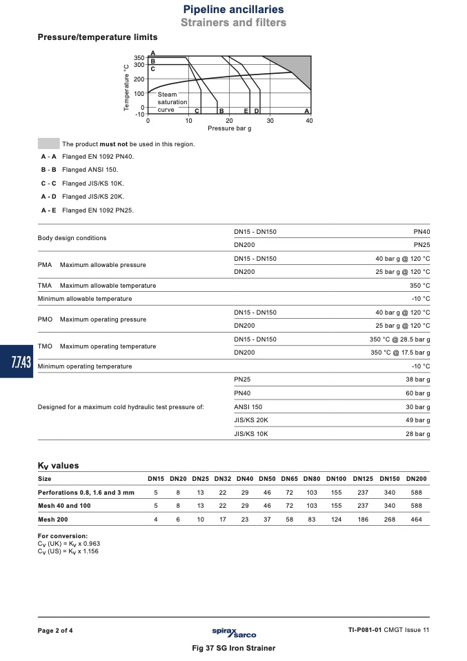
Pressure/temperature limits
������
A
������
������
������
��
������
The product must not be used in this region.
A-A Flanged EN 1092 PN40.
B-B Flanged ANSI 150.
C-C Flanged JIS/KS 10K.
A-D Flanged JIS/KS 20K.
A-E Flanged EN 1092 PN25.
Body design conditions
PMA Maximum allowable pressure
TMA Maximum allowable temperature
Minimum allowable temperature
PMO Maximum operating pressure
TMO Maximum operating temperature
Minimum operating temperature
Designed for a maximum cold hydraulic test pressure of:
��
����
����
����
����
Pressure bar g
DN15 - DN150
DN200
DN15 - DN150
DN200
DN15 - DN150
DN200
DN15 - DN150
DN200
PN25
PN40
ANSI 150
JIS/KS 20K
JIS/KS 10K
PN40
PN25
40 bar g @ 120 °C
25 bar g @ 120 °C
350 °C
-10 °C
40 bar g @ 120 °C
25 bar g @ 120 °C
350 °C @ 28.5 bar g
350 °C @ 17.5 bar g
-10 °C
38 bar g
60 bar g
30 bar g
49 bar g
28 bar g
Kv values
Size
Perforations 0.8, 1.6 and 3 mm
Mesh 40 and 100
Mesh200
For conversion:
Cv (UK) = Kv x 0.963
Cv (US) = Kv x 1.156
DN15 DN20 DN25 DN32 DN40 DN50 DN65 DN80 DN100 DN125 DN150 DN200
5
8
13
22
29
46
72
103
155
237
340
588
5
8
13
22
29
46
72
103
155
237
340
588
4
6
10
17
23
37
58
83
124
186
268
464
Page 2 of 4
TI-P081-01 CMGT Issue 11
Fig 37 SG Iron Strainer
T
e
m
p
e
r
a
t
u
r
e
°
C

