Pipeline ancillaries
Bellows sealed stop valves
Steam
saturation
curve
D
C
B
7.1.15
DN200
Balanced
DN250
Balanced
DN300
Balanced
DN350
Balanced
DN400
Balanced
Unbalanced
Unbalanced
Unbalanced
Unbalanced
Unbalanced
593
735
935
1170
1264
1710
1 804
2 365
2362
3225
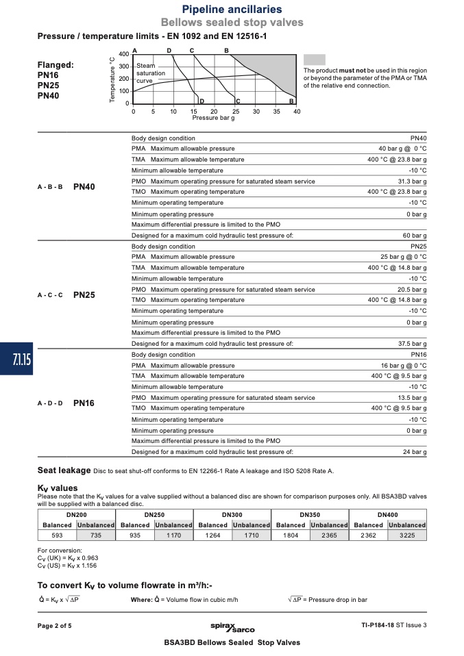
Pressure / temperature limits - EN 1092 and EN 12516-1
400
A
D
C
B
Flanged:
300
PN16
200
PN25
100
PN40
0
A-B-B
PN40
The product must not be used in this region
or beyond the parameter of the PMA or TMA
of the relative end connection.
PN40
40 bar g @ 0 °C
400 °C @ 23.8 bar g
-10 °C
31.3 bar g
400 °C @ 23.8 bar g
-10 °C
0 bar g
60 bar g
PN25
25 bar g @ 0 °C
400 °C @ 14.8 bar g
-10 °C
20.5 bar g
400 °C @ 14.8 bar g
-10 °C
0 bar g
37.5 bar g
PN16
16 bar g @ 0 °C
400 °C @ 9.5 bar g
-10 °C
13.5 bar g
400 °C @ 9.5 bar g
-10 °C
0 bar g
24 bar g
A-C-C
PN25
0
5
10
15
20
25
30
35
40
Pressure bar g
Body design condition
PMA Maximum allowable pressure
TMA Maximum allowable temperature
Minimum allowable temperature
PMO Maximum operating pressure for saturated steam service
TMO Maximum operating temperature
Minimum operating temperature
Minimum operating pressure
Maximum differential pressure is limited to the PMO
Designed for a maximum cold hydraulic test pressure of:
Body design condition
PMA Maximum allowable pressure
TMA Maximum allowable temperature
Minimum allowable temperature
PMO Maximum operating pressure for saturated steam service
TMO Maximum operating temperature
Minimum operating temperature
Minimum operating pressure
Maximum differential pressure is limited to the PMO
Designed for a maximum cold hydraulic test pressure of:
Body design condition
PMA Maximum allowable pressure
TMA Maximum allowable temperature
Minimum allowable temperature
PMO Maximum operating pressure for saturated steam service
TMO Maximum operating temperature
Minimum operating temperature
Minimum operating pressure
Maximum differential pressure is limited to the PMO
Designed for a maximum cold hydraulic test pressure of:
A-D-D
PN16
Seat leakage
Disc to seat shut-off conforms to EN 12266-1 Rate A leakage and ISO 5208 Rate A.
Kv values
Please note that the Kv values for a valve supplied without a balanced disc are shown for comparison purposes only. All BSA3BD valves
will be supplied with a balanced disc.
For conversion:
Cv (UK) = Kv x 0.963
Cv (US) = Kv x 1.156
To convert Kv to volume flowrate in m3/h:-
= Kv x √ ∆P
Where: = Volume flow in cubic m/h
√ ∆P = Pressure drop in bar
Page 2 of 5
TI-P184-18 ST Issue 3
BSA3BD Bellows Sealed Stop Valves
T
e
m
p
e
r
a
t
u
r
e
°
C

