6.1.25
Limiting conditions
Unit design conditions
Maximum motive inlet pressure (steam)
Maximum operating pressure
Maximum backpressure
Maximum operating temperature
Minimum operating temperature
Designed for a maximum cold hydraulic test pressure of:
Materials
No. Part
1
Receiver
2
Ball valves
3
Trap set
4
Strainer
5
Pump - trap
6
Diffuser
7
Base and supporting frame
8
Name - plate
7
3
* 9
* 10
* 11
* 12
Air vent
Check valve
Ball valve
Air eliminator
DN20 to DN50
DN15
DN15 to DN50
DN15
(3⁄4" to 2")
(1⁄2")
(1⁄2" to 2")
(1⁄2")
Material
Carbon steel
Steel (PTFE seals)
Stainless steel (PTFE seals)
SG iron
SG iron
Stainless steel
Carbon steel
Aluminium
Stainless steel
Stainless steel
Stainless steel
Austenitic stainless steel
STS17.2
PC10HP / UBP32
AE50S
8
2
Condensate pumps
Mechanical pumps and pumps traps
APT10
APT14
APT10
APT14
APT10
APT14
APT10
APT14
APT10
APT14
Sizing of the pump-trap is dependent on motive pressure, backpressure
(lift, return system pressure and frictional losses) and process conditions.
For accurate sizing for the application please contact Spirax Sarco.
and APT14HC
and APT14HC
and APT14HC
and APT14HC
and APT14HC
PN10
PN16
4.5 bar g
13.8 bar g
4.5 bar g
13.8 bar g
4 bar g
5 bar g
155°C
198°C
0°C
15 bar g
24 bar g
and APT14HC
Note: For operating temperatures above or below those stated contact Spirax Sarco.
Capacities
*
10
1
2
6
5
4
9
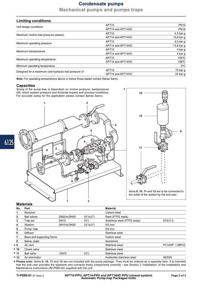
* Please note:
Items 9, 10, 11 and 12 are not included with the pump package. They must be ordered as a separate item. It is intended
that the end user provides the pipework and connects these components correctly - see Section 3 'Installation' of the Installation and
Maintenance Instructions (IM-P680-02) supplied with the unit.
TI-P680-01 ST Issue 2
APT10-PPU, APT14-PPU and APT14HC-PPU (closed system)
Page 2 of 3
Automatic Pump-trap Packaged Units
APT10
APT14
4
12
11
Items 9, 10, 11 and 12 are to be connected to
the outlet of the system by the end user .

