Nominal capacities
Condensate pumps
Mechanical pumps and pumps traps
For full capacity details for a specific application consult Spirax Sarco. To accurately size the pump trap, the following data is required.
1. Installation head available, from the base of the pump trap to the centre line of the heat exchanger / process condensate outlet (m).
If the outlet is mounted vertically, then this should be from the base of the pump to the face of the outlet.
2. Motive steam pressure available to power the pump trap (bar g).
3. Total backpressure in the condensate return system (bar g). See note below.
4. Heat exchanger full-load operating pressure (bar g).
5. Heat exchanger maximum steam load (kg / h).
6. Minimum temperature of secondary fluid ( °C).
7. Maximum controlled temperature of secondary fluid ( °C).
Model
Pump discharge/cycle
1 metre installation head
At: 5 bar g motive pressure
1 bar g total backpressure
APT14
5 litres
Maximum trapping capacity 4 000 kg / h
Maximum pumping capacity 1 100 kg / h
APT14HC and APT14SHC
8 litres
Maximum trapping capacity 9 000 kg / h
Maximum pumping capacity 2 800 kg / h
Note:
The capacities detailed within the above Table are only given as a guide. They are based on the installation parameters shown
in the left hand column.
Achieved capacities will differ if any of the installation parameters change. For specific capacities and application details, contact
Spirax Sarco.
The total lift or backpressure BP (static head plus pressure head in the return system) must be below the motive fluid inlet pressure to
allow pump capacity to be achieved.
BP (backpressure) = (H x 0.098 1) + (P) + (Pf)
Height (H) in metres x 0.098 1 plus pressure (P) bar g in the return line, plus downstream piping friction pressure drop (Pf) in bar.
(Pf can be ignored if the downstream pipework is less than 100 metres to a non-flooded condensate return and has been sized to take
into account the effect of flash steam at the heat exchanger's full-load operating conditions.)
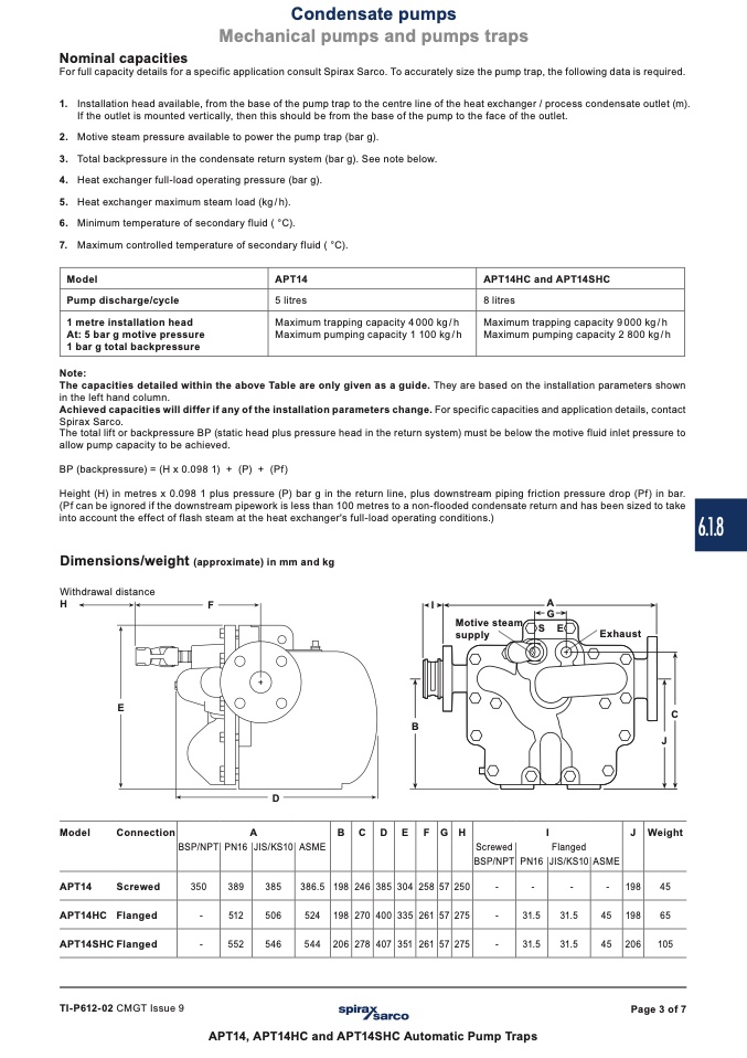
Dimensions/weight (approximate) in mm and kg
Withdrawal distance
H
F
I
A
6.1.8
C
J
E
Model
Connection
APT14
Screwed
APT14HC Flanged
APT14SHC Flanged
D
B
B C D E F G H
TI-P612-02 CMGT Issue 9
Page 3 of 7
A
I
J Weight
BSP/NPT PN16 JIS/KS10 ASME
Screwed
BSP/NPT PN16 JIS/KS10 ASME
350
389
385
386.5 198 246 385 304 258 57 250
-
512
506
524 198 270 400 335 261 57 275
-
31.5
31.5
45 198
65
-
552
546
544 206 278 407 351 261 57 275
-
31.5
31.5
45 206 105
APT14, APT14HC and APT14SHC Automatic Pump Traps
Motive steam
supply
G
S E
Exhaust
Flanged
-
-
-
-
198
45

