6.1.3
D
A
Sizes and pipe connections
Nominal capacities
For full capacity details for a specific application consult Spirax Sarco.
To accurately size the pump trap, the following data is required.
1. Installation head available, from the base of the pump trap to the
centre line of the heat exchanger / process condensate outlet (m).
If the outlet is mounted vertically, then this should be from the
base of the pump to the face of the outlet.
2. Motive steam pressure available to power the pump trap (bar g).
3. Total backpressure in the condensate return system (bar g).
See note below.
4. Heat exchanger full load operating pressure (bar g).
5. Heat exchanger maximum steam load (kg/h).
6. Minimum temperature of secondary fluid (°C).
7. Maximum controlled temperature of secondary fluid (°C).
Size
Inlet
DN20 x DN20
Fluid connections
Outlet
DN20 (3⁄4")
Motive / Exhaust
DN15 (1⁄2")
BSP
NPT
Body design conditions
Maximum motive inlet pressure
Maximum operating pressure
Maximum backpressure
Maximum operating temperature
Minimum operating temperature
Temperature limits (Ambient
)
Designed for a maximum cold hydraulic test pressure of 15.0 bar g
Minimum installation head (from base of pump)
0.2 m
Recommended minimum installation head (from base of pump) 0.3 m
Safety information, installation and maintenance
For full details see the Installation and Maintenance Instructions
supplied with the product.
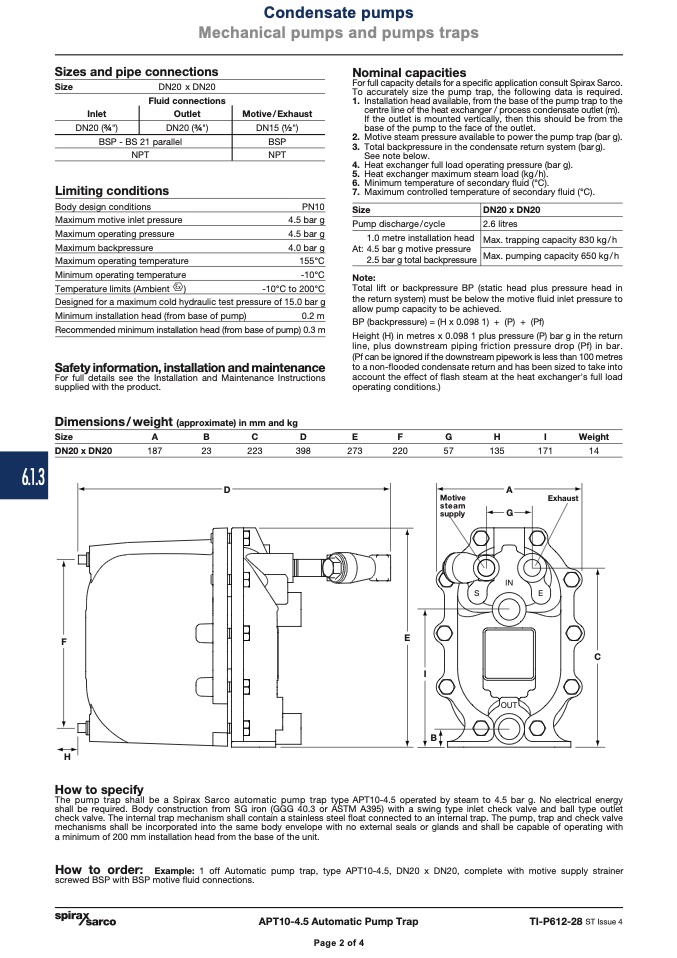
Dimensions/weight (approximate) in mm and kg
Size
A
B
C
D
DN20 (3⁄4")
BSP - BS 21 parallel
NPT
Limiting conditions
DN20 x DN20
187
23
223
398
273
220
57
135
171
14
Exhaust
F
H
How to specify
E
I
B
IN
S
E
OUT
C
Condensate pumps
Mechanical pumps and pumps traps
PN10
4.5 bar g
4.5 bar g
4.0 bar g
155°C
-10°C
-10°C to 200°C
Size
Pump discharge/cycle
1.0 metre installation head
At: 4.5 bar g motive pressure
2.5 bar g total backpressure
Note:
DN20 x DN20
2.6 litres
Max. trapping capacity 830 kg/h
Max. pumping capacity 650 kg/h
Page 2 of 4
The pump trap shall be a Spirax Sarco automatic pump trap type APT10-4.5 operated by steam to 4.5 bar g. No electrical energy
shall be required. Body construction from SG iron (GGG 40.3 or ASTM A395) with a swing type inlet check valve and ball type outlet
check valve. The internal trap mechanism shall contain a stainless steel float connected to an internal trap. The pump, trap and check valve
mechanisms shall be incorporated into the same body envelope with no external seals or glands and shall be capable of operating with
a minimum of 200 mm installation head from the base of the unit.
How to order: Example: 1 off Automatic pump trap, type APT10-4.5, DN20 x DN20, complete with motive supply strainer
screwed BSP with BSP motive fluid connections.
APT10-4.5 Automatic Pump Trap
TI-P612-28 ST Issue 4
Page 2 of 4
Total lift or backpressure BP (static head plus pressure head in
the return system) must be below the motive fluid inlet pressure to
allow pump capacity to be achieved.
BP (backpressure) = (H x 0.098 1) + (P) + (Pf)
Height (H) in metres x 0.098 1 plus pressure (P) bar g in the return
line, plus downstream piping friction pressure drop (Pf) in bar.
(Pf can be ignored if the downstream pipework is less than 100 metres
to a non-flooded condensate return and has been sized to take into
account the effect of flash steam at the heat exchanger's full load
operating conditions.)
E
F
G
H
I
Weight
Motive
steam
supply
G

