Steam traps
Manifolds and insulation jackets
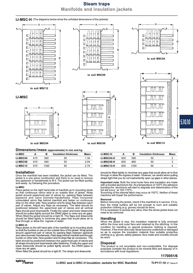
IJ-MSC-H
(The diagrams below show the unfolded dimensions of the jackets)
A
A
B
A
to suit MSC04
A
B
B
to suit MSC12
IJ-MSC
A
to suit MSC08
A
B
to suit MSC04
Dimensions/mass (approximate) in mm and kg
to suit MSC08
to suit MSC12
Insulation thickness Mass
50
2
50
3
50
4
B
B
IJ-MSC
A
IJ-MSC04
615
IJ-MSC08
615
IJ-MSC12
615
Installation
B
Insulation thickness
560
50
940
50
1320
50
Mass
1.34
2.04
2.74
IJ-MSC-H
IJ-MSC04-H
835
590
IJ-MSC08-H
835
960
IJ-MSC12-H
835
1330
When fitted the jacket should be a tight fit. The straps and drawcords
IJ-MSC and IJ-MSC-H Insulation Jackets for MSC Manifold
TI-P117-10 ST Issue 6
A
B
Once the manifold has been installed, the jacket can be fitted. The
jacket is a one piece construction and there is no need to remove
any pipework or handwheels to fit it. The jacket can be fitted quickly
and easily by following this procedure.
IJ-MSC
Place jacket on the right hand side of manifold up to mounting studs
so that continuous velcro strip is on outside face of jacket. Wrap
jacket around uppermost pair of valves by passing flaps between
pipework and valve bonnets/handwheels. Pass horizontal
uninsulated velcro flap behind manifold and fasten on continuous
strip on the other side. Now position and fix large flap between each
pair of valves. Adjust any flaps as necessary. The label should be
positioned between the uppermost pair of valves and all vertical
flaps should point downwards. Finally the upper and lower drawcords
should be pulled tightly around the DN40 pipes to close any air gaps.
When fitted the jacket should be a tight fit. The flaps and drawcords
should be fitted tightly to minimise any gaps that would allow air to
flow through or allow the ingress of water.
IJ-MSC-H
Place jacket on the left hand side of the manifold up to mounting studs
so that the buckles on are on the outside face of the jacket. Wrap jacket
around uppermost pair of valves by passing flaps between pipework
and valve bonnets / handwheels. Pass strap behind manifold and through
buckle on other side. Now position and fix large flap as necessary. The
label should be positioned between the uppermost pair of valves and
all straps should point downwards after fastening. Finally the upper and
lower drawcords should be pulled tightly around the DN40 pipes to
close any air gaps.
should be fitted tightly to minimise any gaps that would allow air to flow
through or allow the ingress of water. However, be careful when pulling
straps tight that you do not inadvertently open up gaps in other places.
Important note: Both the inner/outer face and insulation are made
with a bonded aluminium foil. At a temperature of 120°C the adhesive
bonding the aluminium will start to degrade and delamination of the
foil will occur at 150-170°C.
Scorching of the internal fabric may occur at 150°C. Neither of these
reactions will impair the performance.
Removal
Before removing the jacket, check if the manifold is in service. If it is,
then the metal surface will be hot enough to burn and suitable
protective clothing (e.g. gloves) should be worn.
If it is necessary to access any valve, then the whole jacket does not
need to be removed.
Handling
When the jacket is new, the insulation material is fully enclosed
within the inner and outer face and retained by the stitching. In this
condition for handling no special protective clothing is required.
However, if the inner and outer faces become unstitched or damaged
so as to expose the insulation material then suitable protective
clothing (e.g. gloves, safety glasses, face mask and overalls) should
be worn.
Disposal
This product is not recyclable and non-combustible. For disposal
purposes consider the product to be mineral fibre and dispose of in
accordance with local regulations.
1170051/6
5.10.10

