Steam traps
Local regulations may restrict the use of this product to below the conditions quoted.
Swivel connectors and traps
In the interests of development and improvement of the product, we reserve the right to change the specification without notice. © Copyright 2017
TI-F01-37
CMGT Issue 2
Piping Installation Diagrams
for Compact Steam Trapping Stations
Description
The diagrams and images shown on this document depict the piping arrangements of the standard range of Spirax Sarco pipeline
connectors and traps.
Other special configurations can also be supplied to meet individual customer needs - consult Spirax Sarco.
Pipeline connectors can be used with the 'Universal' range of traps supplied by Spirax Sarco.
For full details on compatible universal traps, see Page 4.
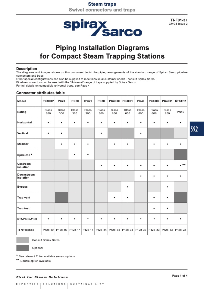
Connector attributes table
Model
PC10HP
PC20 IPC20 IPC21 PC30
PC3000
PC3001 PC40 PC4000 PC4001 STS17.2
Rating
Class
600
Class
300
Class
300
Class
300
Class
600
Class
600
Class
600
Class
600
Class
600
Class
600
PN40
Horizontal
•
• • • •
•
• • • • •
Vertical
•
• • •
Strainer
• • •
•
• • • •
Spira-tec
* • •
Upstream
isolation
•
•
• • • • • **
Downstream
isolation
• • • •
Bypass
• •
Trap vent
•
• • •
Trap test
• •
STAPS ISA100
•
• • • •
•
• • • • •
TI reference
P128-10
P128-15 P128-17 P128-17 P128-34
P128-34
P128-34 P128-33 P128-33 P128-33 P128-22
Consult Spirax Sarco
Optional
*
See relevant TI for available sensor options
**
Double option available
Page 1 of 4
5.9.2

