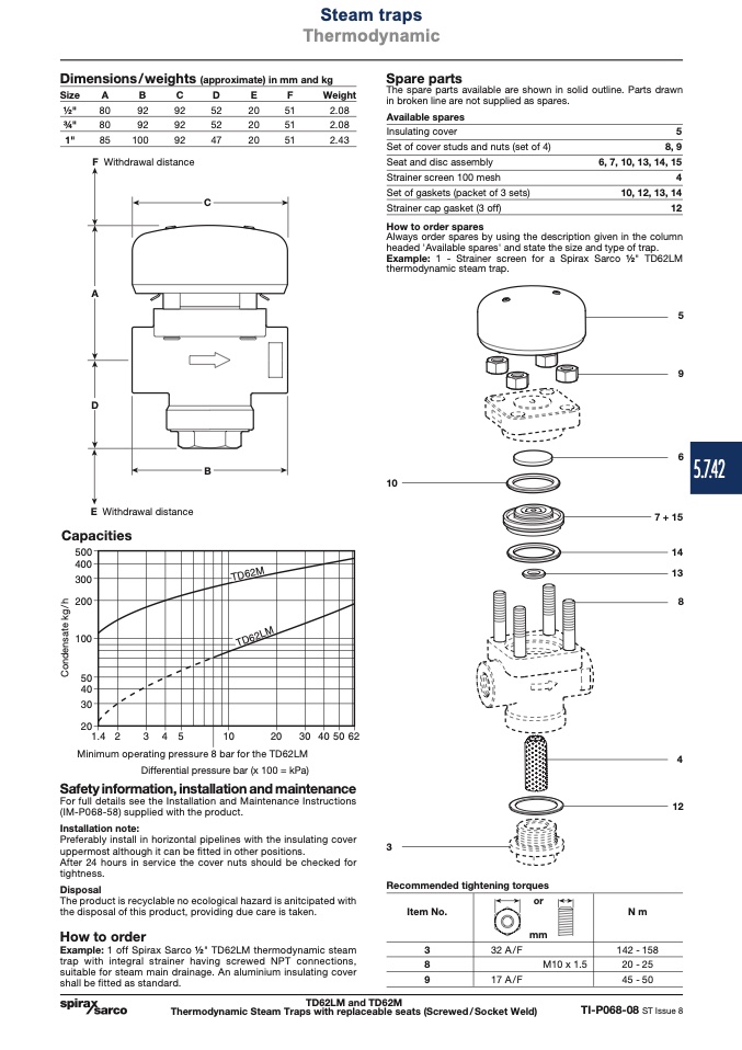
Dimensions/weights (approximate) in mm and kg
Size
A
B
C
D
E
F
Weight
Spare parts
The spare parts available are shown in solid outline. Parts drawn
in broken line are not supplied as spares.
1⁄2"
80
92
92
52
20
51
2.08
3⁄4"
80
92
92
52
20
51
2.08
1"
85
100
92
47
20
51
2.43
Available spares
Insulating cover
Set of cover studs and nuts (set of 4)
Seat and disc assembly
Strainer screen 100 mesh
Set of gaskets (packet of 3 sets)
Strainer cap gasket (3 off)
How to order spares
5
8, 9
6, 7, 10, 13, 14, 15
4
10, 12, 13, 14
12
F Withdrawal distance
A
D
C
E Withdrawal distance
Capacities
���
���
���
���
���
��
��
��
��
����
�
�
�
��
�
�
��������
B
5
9
6
5.7.42
7 + 15
14
13
8
4
12
Minimum operating pressure 8 bar for the TD62LM
Differential pressure bar (x 100 = kPa)
Safety information, installation and maintenance
For full details see the Installation and Maintenance Instructions
(IM-P068-58) supplied with the product.
Installation note:
Preferably install in horizontal pipelines with the insulating cover
uppermost although it can be fitted in other positions.
After 24 hours in service the cover nuts should be checked for
tightness.
Disposal
The product is recyclable no ecological hazard is anitcipated with
the disposal of this product, providing due care is taken.
How to order
Example: 1 off Spirax Sarco 1⁄2" TD62LM thermodynamic steam
trap with integral strainer having screwed NPT connections,
suitable for steam main drainage. An aluminium insulating cover
shall be fitted as standard.
3
Recommended tightening torques
Steam traps
Thermodynamic
�����
C
o
n
d
e
n
s
a
t
e
k
g
/
h
������
TD62LM and TD62M
Thermodynamic Steam Traps with replaceable seats (Screwed/Socket Weld)
TI-P068-08 ST Issue 8
Always order spares by using the description given in the column
headed 'Available spares' and state the size and type of trap.
Example: 1 - Strainer screen for a Spirax Sarco 1⁄2" TD62LM
thermodynamic steam trap.
10
Item No.
3
8
9
or
mm
N m
32 A / F
17 A/F
M10 x 1.5
142 - 158
20 - 25
45 - 50

